Product Description
I. Product Overview
GE DS200UCPBG6AFB is a core control board in the Mark V series steam turbine control system of General Electric (GE), specifically designed for real-time control and status management of industrial-grade steam turbines and gas turbines. As the "control core" of the Mark V system, it undertakes key responsibilities including control logic execution, equipment status monitoring, emergency protection triggering, and system collaborative scheduling. It is the core hardware carrier for ensuring the safe, efficient, and stable operation of large-scale power equipment, and is widely used in industrial scenarios with extremely high requirements for control accuracy and reliability, such as power generation, petrochemicals, and metallurgy.
This board adopts a standard 6U VME industrial board form factor (approximately 160mm in height, 233mm in width, and 28mm in thickness), with no independent operation panel. It achieves high-speed data interaction with power modules, I/O modules, and communication modules through the system backplane. The component layout on the board surface complies with industrial-grade anti-interference standards; key control chips (such as microprocessors and FPGAs) are equipped with metal shields, and the pin soldering process meets the IPC-A-610 Class 3 industrial standard. It can withstand long-term high-load operation and complex electromagnetic environments (such as motor start-stop and high-frequency interference from frequency converters), ensuring the stability and durability of control functions and adapting to harsh operating conditions in industrial sites.

II. Core Functional Features
1. High-Performance Control Logic Calculation
DS200UCPBG6AFB is equipped with a 32-bit high-performance embedded microprocessor (with a maximum main frequency of 600MHz), which has strong real-time computing capabilities and supports the parallel execution of up to 800 complex control logic instructions. Its built-in dedicated control algorithm library covers core functions such as turbine start-stop control, speed closed-loop regulation, load distribution, valve control, and emergency shutdown (ETS) logic. It can automatically switch control strategies according to the unit's operating conditions (such as cold start, hot start, normal operation, and shutdown maintenance), ensuring the control accuracy of the unit throughout its life cycle (speed control error ≤ ±0.15% of rated speed, load regulation response time ≤ 120ms). At the same time, the board supports user-defined control logic; users can write ladder diagrams and Function Block Diagram (FBD) programs through GE's dedicated configuration software (such as ToolboxST) to adapt to the personalized control needs of different projects.
2. Multi-Dimensional Equipment Status Monitoring
The board integrates 24 digital input (DI) channels, 16 digital output (DO) channels, 8 analog input (AI) channels, and 4 analog output (AO) channels, which can be directly connected to on-site equipment such as temperature sensors (thermocouples/RTDs), pressure transmitters, vibration sensors, and valve position feedback devices. It supports the collection of standard industrial signals such as 4-20mA and 0-10V, with an analog input accuracy of ±0.1% FS and a digital input response time of ≤1ms, enabling real-time capture of key operating parameters of the unit (such as exhaust temperature, lube oil pressure, rotor vibration value, and valve opening). Through built-in data filtering and calibration algorithms, abnormal data such as electromagnetic interference and signal fluctuations can be eliminated, ensuring the authenticity and validity of monitoring data and providing a reliable basis for the execution of control logic.
3. Highly Reliable Redundant Control and Protection
To meet the high requirements for control reliability in industrial scenarios, DS200UCPBG6AFB adopts a dual redundancy design:
Control Logic Redundancy: The board has a built-in dual-processor core that executes the same control program in parallel and compares the calculation results in real time. If a deviation occurs, it automatically switches to the normal core to avoid control failure caused by a single processor fault.
I/O Signal Redundancy: Key analog inputs (such as speed and lube oil pressure) support "two-out-of-three" and "one-out-of-two" redundant configurations. When a sensor signal in one channel is abnormal, it automatically switches to the backup signal to prevent false triggering of protection actions.
For key turbine faults (such as overspeed, overtemperature, and low lube oil pressure), the board can quickly execute emergency shutdown commands, cut off fuel supply, or trigger trip solenoid valves, with a response time of ≤60ms, minimizing the risk of equipment damage.
4. Flexible Communication and System Collaboration
DS200UCPBG6AFB is equipped with rich communication interfaces to support efficient data interaction with other modules in the system and external equipment:
It realizes high-speed data transmission (with a rate of 80MB/s) with power modules, I/O modules, and communication modules through the VME64x backplane bus, ensuring collaborative response between modules.
It is equipped with 1 RS485 serial port (supporting Modbus RTU protocol) that can connect to third-party intelligent equipment (such as smart meters and frequency converters).
It also supports connection to the Human-Machine Interface (HMI) of the Mark V system, enabling real-time upload of unit operating data (such as real-time working conditions, alarm information, and historical trends) and receiving manual control commands from operators (such as manual start-stop and manual load adjustment). This realizes a dual management mode of "automatic control + manual intervention" and improves the operational flexibility of the system.
III. Key Technical Parameters
1. Electrical Parameters
Power Supply Requirements: The input voltage is ±15V DC (for analog circuits) and +5V DC (for digital circuits), with an allowable voltage fluctuation range of ±5%; the maximum power consumption is ≤30W. The board surface is integrated with aluminum heat sinks, and natural heat dissipation is sufficient to meet the needs of high-load operation, with an operating temperature of ≤60℃.
Input/Output Specifications:
Analog Input (AI): 8 channels, supporting 4-20mA/0-10V, input impedance ≥100kΩ, accuracy ±0.1% FS;
Digital Input (DI): 24 channels, supporting 24V DC, compatible with dry contacts/wet contacts, response time ≤1ms;
Analog Output (AO): 4 channels, supporting 4-20mA, output load ≤500Ω, accuracy ±0.2% FS;
Digital Output (DO): 16 channels, relay output, contact rating 2A/250V AC, supporting normally open/normally closed mode switching.
Anti-Interference Performance: Complies with the IEC 61000-6-2 industrial anti-interference standard, with ±2kV Electrostatic Discharge (ESD) protection, ±1kV Electrical Fast Transient (EFT) protection, and radio frequency radiation immunity of ≥10V/m (80-1000MHz), enabling stable operation in complex electromagnetic environments.
2. Environmental Parameters
Operating Temperature: -20℃~60℃, supporting wide-temperature operation and adapting to scenarios such as high-temperature workshops and outdoor control cabinets;
Storage Temperature: -40℃~85℃, with no risk of component aging or pin corrosion during long-term storage;
Humidity: 5%~95% (non-condensing), the board surface is coated with a moisture-proof insulating layer, allowing use in high-humidity and high-salt-spray coastal environments;
Vibration Protection: Complies with the IEC 60068-2-6 standard, capable of withstanding sinusoidal vibration with a frequency of 10-500Hz and an acceleration of 5g; complies with the IEC 60068-2-27 standard, capable of withstanding an impact of 50g acceleration (11ms pulse), avoiding interface loosening and component damage caused by equipment operation vibration or transportation impact.
3. Physical and Status Indication Parameters
Dimensions: 6U VME board form factor (160mm×233mm×28mm), compatible with standard 19-inch industrial control cabinet installation, and supporting hot swapping (requires Mark V system authorization);
LED Indicators: 6 status lights (PWR: Power status, green; RUN: Operation status, green; ALM: Alarm status, yellow; ERR: Fault status, red; DI/AO: I/O status, green). The RUN light stays on to indicate normal operation and blinks to indicate logic calculation in progress; the ALM light is on to indicate detected equipment abnormalities (non-emergency faults); the ERR light is on to indicate board hardware faults;
Backplane Interface: 1 VME64x backplane interface, used for communication with other modules in the system, with a transmission rate of 80MB/s. It supports interrupt requests, bus arbitration, and data synchronization to ensure collaborative response between modules.
IV. Common Faults and Troubleshooting Methods
1. Board No Response (All Indicators Off)
Symptom: After the board is powered on, all LED indicators are off. The system cannot detect the module, the turbine control function is completely invalid, and only the manual emergency shutdown button is operable.
Possible Causes: ① Power supply line faults (such as damaged ±15V/±5V power modules, poor contact of power supply cables); ② Loose or damaged board power interface (such as oxidized backplane gold fingers, bent power pins); ③ Internal power circuit faults of the board (such as burned fuses, damaged power chips LM1117).
Troubleshooting Methods: ① Use a multimeter to measure the output voltage of the power module to confirm whether it meets the ±15V DC/±5V DC requirements. If the power module is damaged, replace it with a power module of the same model (such as GE DS200PSCAH1A); ② Power off, pull out the board, wipe the backplane gold fingers with anhydrous ethanol, check whether the power pins are bent, and reinsert the board tightly to ensure good contact; ③ Open the board casing (operate with power off), check whether the fuse (1A/250V) in the power circuit is burned. If burned, replace it with a fuse of the same specification and test after powering on; if the fuse is burned again, replace the power chip LM1117 (operation by GE-certified engineers is required).
2. Abnormal Analog Acquisition (Large Data Deviation/No Data)
Symptom: The monitoring system shows that the analog data (such as temperature and pressure) of one or more channels deviates from the actual value by more than 10%, or displays "no data", leading to misjudgment of control logic (such as false triggering of load reduction).
Possible Causes: ① Sensor faults (such as broken thermocouples, invalid calibration of pressure transmitters); ② Interference in analog input lines (such as parallel routing with power cables, signal distortion caused by electromagnetic interference); ③ Faults in the board's analog input circuit (such as damaged signal conditioning chips AD8221, leaking filter capacitors); ④ Lost analog calibration parameters (such as incorrect gain and offset parameters).
Troubleshooting Methods: ① Disconnect the sensor from the board, input a standard signal (such as 4mA/20mA) with a signal generator. If the monitoring data returns to normal, replace the sensor with the same model and recalibrate it; ② Replan the routing path of analog lines, keep a distance of ≥30cm from power cables, install metal shielding tubes and ground them (ground resistance ≤4Ω); ③ Use an oscilloscope to measure the signal waveform of the analog input circuit. If the waveform is distorted, replace the signal conditioning chip AD8221; ④ Enter the board calibration interface (via GE ToolboxST software) and recalibrate the gain and offset of the analog input channels to ensure data accuracy.
3. No Digital Output Action (DO Interface Failure)
Symptom: The board sends a digital output command (such as controlling a valve to open), but the corresponding actuator (such as a solenoid valve) does not act. The monitoring system displays "normal output", but the actual equipment does not respond, affecting the turbine control process.
Possible Causes: ① Digital output line faults (such as loose terminal blocks, broken cables); ② Actuator faults (such as burned solenoid valve coils, stuck valves); ③ Faults in the board's digital output circuit (such as damaged relays, faulty driver chips ULN2803); ④ Control logic errors (such as output commands blocked by interlock conditions).
Troubleshooting Methods: ① Check the wiring of digital output lines, fasten the terminals, and use a multimeter to measure the continuity of the cables; ② Supply power to the actuator independently (such as 220V AC) and test whether it acts. If it does not act, replace the actuator (such as a solenoid valve); ③ Measure the output voltage of the board's DO interface (such as 220V AC). If there is no voltage output, replace the internal relay or driver chip ULN2803 of the board; ④ Check the control logic program (via configuration software) to see if there are interlock conditions (such as low pressure blocking the valve opening command), and remove unreasonable interlocks or fix logic errors.
4. False Triggering of Emergency Shutdown (ERR Light On + Shutdown Action)
Symptom: The turbine operating parameters are normal (speed 3000rpm, temperature 535℃, pressure 16.7MPa), but the board suddenly triggers an emergency shutdown, and the ERR light is on, resulting in unplanned shutdown and affecting production continuity.
Possible Causes: ① Incorrect emergency protection threshold settings (such as overspeed protection threshold set to 3100rpm, which is triggered by normal fluctuations); ② Redundant control logic faults (such as excessive deviation in calculation results of dual processors, misjudged as hardware faults); ③ Interference in key sensor signals (such as vibration sensors affected by electromagnetic interference, outputting false high-value signals); ④ Errors in the board's FPGA logic program (such as false triggering of protection logic).
Troubleshooting Methods: ① Enter the board's protection parameter configuration interface, verify the emergency protection thresholds (such as overspeed protection threshold set to 3300rpm), correct the incorrect thresholds, and restart the board; ② Test the redundant processor function, simulate a single processor fault, and observe whether false shutdown is triggered. If there is a fault, reflash the processor program; ③ Check the shielding and grounding of sensor cables (single-ended grounding, ground resistance ≤4Ω), and install signal isolators to reduce interference; ④ Contact GE technical support to obtain the latest firmware of the FPGA logic program, and reflash the program through the JTAG interface to fix logic errors.

 1YrAnshun, Guizhou, China
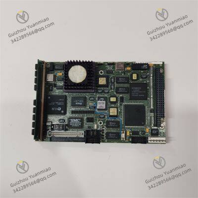


 yezi
Hi there! Welcome to my shop. Let me know if you have any questions.
yezi
Hi there! Welcome to my shop. Let me know if you have any questions.