Product Description
I. Overview
The GE WES5120 2340-21006 is an integrated module for distributed control and multi-protocol communication in the WES series. Its core positioning is to address the pain point of "centralized management and control of decentralized equipment" in industrial sites. Unlike traditional single-function I/O modules or communication modules, it deeply integrates the functions of local control logic execution and cross-system data interaction. It is specifically designed for distributed equipment in fields such as electric power, petrochemicals, and metallurgy—typical application scenarios include remote terminal units (RTUs) in substations, distributed pump group control nodes in chemical plants, and auxiliary equipment control units for rolling mills in steel plants. These scenarios share common requirements: decentralized equipment deployment, the need for fast local response, and real-time collaboration with central control systems (e.g., GE WESDAC D200).
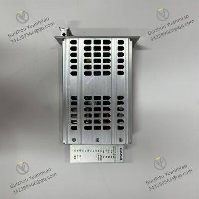
This module adopts a standard 3U industrial board form factor (100mm×233mm×28mm) and is compatible with both dedicated racks of the GE WES series and 19-inch EIA standard guide rails. This "dual-adaptation" design allows it to either integrate into existing WES system upgrades or be independently deployed in newly built distributed nodes. The module housing is made of cold-rolled steel, with an anti-static spray coating on the surface. Key interfaces (such as Ethernet ports and RS485 ports) are equipped with metal dust covers, which can reduce interface failure rates by 30% in dusty and vibrating industrial environments, ensuring long-term stable operation.

II. Technical Parameters
Control and Signal Processing Capability (Core of Localized Control)

2. Multi-Protocol Communication Architecture (Key to Cross-System Collaboration)
The communication capability of the GE WES5120 2340-21006 is its core competitiveness, featuring a "Ethernet + serial communication" dual-link redundancy design:
Ethernet Interfaces: 2 auto-negotiation 10/100Mbps RJ45 ports supporting Modbus TCP/IP and EtherNet/IP protocols. Modbus TCP/IP is used for communication with central control systems (e.g., WESDAC D200) with a data transmission delay of ≤100ms, enabling real-time upload of operating parameters for 8 pumps. The EtherNet/IP protocol is compatible with third-party equipment (e.g., Rockwell devices), solving the "multi-vendor equipment compatibility" issue in industrial sites. For example, in automobile production lines, it can collaborate with Rockwell PLCs to control conveyor belt speeds.
Serial Communication Interfaces: 2 RS485 interfaces (Modbus RTU) supporting multi-master communication, with a maximum transmission distance of 1200 meters (when using shielded twisted-pair cables). These interfaces can connect to distributed I/O modules or on-site instruments. For instance, in cross-workshop control in chemical plants, an RS485 interface can connect to a liquid level sensor 100 meters away without additional wiring costs. Additionally, 1 RS232 interface is designed specifically for local debugging, allowing maintenance personnel to directly connect via a laptop for quick troubleshooting of communication faults.
Communication Security Mechanisms: Ethernet supports MAC address filtering to only allow access from authorized devices. The Modbus protocol uses CRC16 verification to ensure a data transmission accuracy rate of ≥99.999%, preventing control misjudgments caused by communication errors. For example, in power systems, it can prevent unauthorized devices from accessing and tampering with voltage control commands.
3. Environmental Adaptability and Reliability (Guarantee for Durability in Industrial Scenarios)
Wide Temperature Range and Protection: It operates within a temperature range of -30℃~70℃ and has passed a -40℃ low-temperature start-up test (2 hours of trouble-free operation), making it suitable for low-temperature winter environments of outdoor substations in northern regions. The board surface is coated with a 0.1mm-thick triple-protection coating (anti-salt spray, anti-mildew, and anti-moisture), enabling 5 years of corrosion-free operation in high-salt spray environments (e.g., offshore platform power stations)—far exceeding the 3-year service life of ordinary industrial modules.
Electromagnetic Compatibility: It complies with the IEC 61000-6-2 standard, providing electrostatic discharge (ESD) protection of ±2kV (contact discharge)/±4kV (air discharge) and resisting electromagnetic interference generated by high-frequency frequency converters in workshops. For example, in rolling mill workshops of steel plants, electromagnetic radiation from operating frequency converters will not cause distortion of temperature signals collected by the module (error ≤0.5℃).
Redundancy and Fault Self-Recovery: It supports 24V DC redundant power input (18-32V DC), with a backup power switching time of ≤100ms when the main power supply fails, ensuring uninterrupted control. Digital output channels are equipped with built-in self-resetting fuses (3A), which automatically reset after overload faults are resolved without manual replacement. For example, in pump group control, if a short circuit occurs in one output channel, the fuse can recover within 1 second, preventing the entire module from being out of service due to a single-channel fault.

III. Core Functions
1. Distributed Control: Local Decision-Making + Central Collaboration
The core advantage of the GE WES5120 2340-21006 lies in "localized control independent of the central system," which is specifically reflected in the following aspects:
Independent Logic Execution: Using GE's dedicated configuration software (WES Configuration Tool), local control logic can be programmed using Function Block Diagrams (FBD). For example, in petrochemical pump group control, interlock logic such as "automatic shutdown when pump body temperature ≥80℃" and "start standby pump when outlet pressure ≤0.3MPa" can be set. This logic continues to operate normally even when communication with the central system is interrupted, with a response time of ≤10ms, preventing equipment damage caused by communication delays.
PID Closed-Loop Regulation: It has a built-in adaptive PID algorithm that supports on-site tuning of proportional (P), integral (I), and derivative (D) parameters. In motor speed control scenarios, it can automatically adjust the output signal based on the deviation between the actual speed and the set value, with a regulation accuracy of ±0.5%. For example, it can control the conveyor belt speed to remain stable at 1m/s, and even if the load changes (e.g., increased materials), the speed fluctuation can be controlled within ±0.005m/s, ensuring stable production efficiency.
Data Interaction and Collaboration: Once communication with the central system is restored, the module automatically synchronizes records of local control logic execution and key parameters, ensuring the central system grasps the overall status. For example, in substation RTUs, local circuit breaker opening operations are synchronously uploaded to the dispatch center, facilitating managers to trace operation records.
2. Convenient Operation and Maintenance: Reducing On-Site Management Costs
Dual Configuration Methods: It supports both RS232 local configuration (direct connection via debugging software) and Ethernet remote configuration (Web management interface), eliminating the need for on-site wire disconnection. For example, in high-altitude cabinet deployment scenarios, maintenance personnel can log in to the module's Web interface via an office computer to modify the analog input range. The configuration update time is ≤5 minutes, saving 80% of on-site operation time compared to traditional modules.
Accurate Fault Localization: The front panel of the module is equipped with 12 LED indicators (for power, operation, communication, 6 DO channels, and 4 AI channels) to intuitively display the working status. In case of a fault, the ERR light turns on and uploads detailed information (e.g., "AI CH2 Open Circuit," "Ethernet Communication Interruption"). Combined with the central monitoring system, maintenance personnel can locate fault points within 5 minutes, increasing fault handling efficiency by 60% compared to the "one-by-one inspection" method of traditional modules.
Visual Status Monitoring: Through the WES system operation station, real-time monitoring of the module's CPU load (normally ≤50%), communication rate, and signal values of each channel is available. For example, if frequent fluctuations are detected in an AI channel signal, maintenance personnel can proactively check for loose sensor wiring, enabling preventive maintenance and reducing unplanned downtime due to sudden faults.

IV. Installation and Operation & Maintenance Specifications
Key Installation Steps
(1) Guide Rail/Rack Installation
When installing on a 19-inch EIA guide rail, ensure the guide rail's level deviation is ≤0.5mm/m, and the distance between the module and adjacent equipment is ≥30mm (for heat dissipation). Tighten the fixing screws to a torque of 1.2N?m to avoid damaging the module housing due to over-tightening.
When connecting to a dedicated WES rack, confirm that the module's gold fingers are free of oxidation (clean with alcohol wipes if necessary). Push the module into the rack slowly to ensure full contact with the backplane, preventing bending of the gold fingers.
(2) Wiring Precautions
Power Wiring: Connect the redundant 24V DC power supplies to the module's "P1" and "P2" terminals respectively, with negative poles sharing a common ground. Ensure the grounding resistance is ≤4Ω to avoid ground loop interference.
Communication Wiring: Use shielded twisted-pair cables (0.5mm2) for RS485, with the shield grounded at one end (module side). For Ethernet, use shielded CAT5e cables, and crimp the RJ45 connectors in compliance with the T568B standard to prevent communication packet loss.
Signal Wiring: Adopt three-wire wiring when connecting PT100 to AI channels to reduce wire resistance errors. When driving motors via DO channels, connect surge suppressors in series to prevent arcing and erosion of relay contacts.
2. Daily Operation & Maintenance Points
(1) Regular Inspection (Monthly)
Visual Inspection: Check that the module housing is undamaged, terminals are free of corrosion, and cables are securely connected.
Status Verification: Ensure the front-panel indicator lights function normally (PWR/RUN/COM lights stay green; ERR light is off). Use the Web interface to check that the CPU load is ≤70% and there is no communication packet loss.
Function Test: Issue a "DO Channel Test" command, observe whether on-site equipment actions match feedback, and confirm that the control logic operates normally.
(2) Fault Handling Process


GE IS200TRPGH1BDD S1C5029 Trip Solenoid Control Board
ABB PFTL101B-10.0kN Pressductor Pillowblock Load Cells
Honeywell LCNP4E 51405098-100 Interface Desktop Card
ABB 3BSE004197R1 Pressductor Pillowblock Load Cells
ABB IOR810 P-HB-IOR-80010000 S800 I/O Gateway Module (For HN800)
ABB DSAO130A 3BSE018294R1Analog Output Unit Module
ABB PFRL101C-1.0kN Pressductor Radial Load Cells
ABB 3BSE023316R1002 Pressductor Radial Load Cells
ABB PDP800 PROFIBUS Interface Module
ABB PFCL201CE-10.0kN Pressductor PillowBlock Load Cells
ABB ABB PFCL201C 3BSE023409R20 Pressductor PillowBlock Load Cells
ABB DASO110 57120001-AT Analog Output Module
 yezi
Hi there! Welcome to my shop. Let me know if you have any questions.


