
- Guizhou Yuanmiao Automation Equipment Co., Ltd.
-
 1YrAnshun, Guizhou, China
 - Main products: ABB Triconex Foxboro LAM, Bentley Motorola Schneider, Kollmorgen HIMA ALSTOM, Reliance GE HONEYWELL NI、ICS
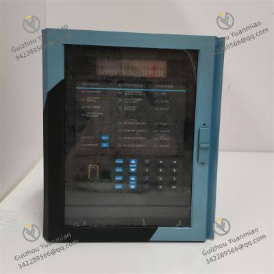


GE SR745-W2-P1-G1-HI-A-L-R-E Transformer Protection System
- T/T PayPal Western Union
You May Like
Product Details
| Material | Other, Global universal model | Condition | Other, Global universal model | |
| Task | Other, Global universal model | Mathematical Model | Other, Global universal model | |
| Signal | Other, Global universal model | Customized | Non-Customized | |
| Structure | Other, Global universal model | Operating temperature | - 40℃ to 70℃ | |
| Humidity | 5% - 95% (non - condensing) |
Product Description

Company Profile
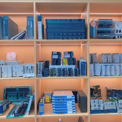
Main products: Covering globally renowned brands: Bently Nevada, Triconex, Woodward, Foxboro, Westinghouse, Reliance, Schneider Modicon, ABB, AB (Allen-Bradley), Motorola, GE Fanuc, Yaskawa, Bosch Rexroth Rexroth, ACSO, YOKOGAWA, Rexroth, NI, ICS Triplex, Kollmorgen, Mitsubishi, MOOG, Emerson, B&R B&r, SST, ALSTOM, KUKA EPRO, LAM HIMA dark Horse, HONEYWELL, prosoft, AMAT, SIEMENS, etc. The product categories include: DCS system accessories, robot system spare parts, large servo system spare parts, etc., which are widely used in power, chemical, metallurgy, intelligent manufacturing and other fields.
Contact Us
- Guizhou Yuanmiao Automation Equipment Co., Ltd.
- Contact nameyezi Chat Now
- AddressXixiu District, Anshun, Guizhou
Product Categories
New Products
-
Prosoft 5202-DFNT-MCM4 Communications Module
-
Emerson KJ4110X1-BA1 Programmable Logic Controller
-
ABB 1MRB15004R0001 Communication Module
-
ABB 1MRB150005R0001 Digital I/O Module
-
HIMA 80105 984080105 Communication Module
-
ABB 1MRK001967-AA Control Card
-
ABB 1MRB150020R1102 Ccontroller Module
-
ABB 1MRB150038R1 Power Supply Module
-
ABB 1MRB150051R1 Power Supply Module
-
ABB PPD513A-23-111615 magnetic excitation controller
-
TRICONEX Safety Instrumented System (SIS) 4351B control module
-
Bentley Nevada 3500/22M Transient data interface module
-
Bently Nevada 3500/15-05-05-00 power module
-
Triconex 3009 processor module
-
ABB GFD563A102 3BHE046836R0102 Excitation Convection Interface Module
-
ABB PPD117A3011 3BHE030410R3011 Excitation Controller
-
ABB PCD231B101 3BHE025541R0101 Excitation Unit Controller
-
ABB 5SHY3545L0010 3BHE009681R0101 High-Voltage Thyristor Module
Find Similar Products By Category
- Electrical & Electronics > Electrical Control System
Product Tags:
Guizhou Yuanmiao Automation Equipment Co., Ltd.

- Please Enter your Email Address
- Please enter the content for your inquiry.
We will find the most reliable suppliers for you according to your description.
Send Now-
 yezi
Hi there! Welcome to my shop. Let me know if you have any questions.
yezi
Hi there! Welcome to my shop. Let me know if you have any questions.
Your message has exceeded the limit.
- Contact supplier for lowest price
- Customized Request
- Request Sample
- Request Free Catalogs
Your message has exceeded the limit.
-
Purchase Quantity
-
*Sourcing Details
Your inquiry content must be between 10 to 5000 characters.
-
*Email
Please enter Your valid email address.
-
Mobile