Product Description
I. Product Overview
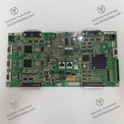
The GE IS210MACCH1AGG is a core main control board in the Mark VIe series control system, specifically designed for the precise control and status management of industrial-grade steam turbines, gas turbines, and combined cycle units. As the "computational core" of the Mark VIe system, it undertakes key responsibilities including control logic execution, real-time data processing, and equipment collaborative scheduling, serving as a core hardware carrier to ensure the safe, efficient, and stable operation of large-scale power equipment.
In terms of physical form, this board adopts a standard 6U VME industrial board design with a compact overall size (approximately 160mm in height, 233mm in width, and 25mm in thickness). It has no independent operation panel and achieves high-speed data interaction with other modules through the system backplane. The component layout on the board surface complies with industrial-grade anti-interference standards; key chips are protected by metal shields, and the pin soldering process meets military-grade reliability requirements. It can adapt to long-term high-load industrial operating environments and is widely used in fields such as power generation, petrochemicals, and metallurgy, where extremely high requirements are placed on equipment control accuracy and stability.

II. Core Functional Features
1. High-Performance Control Logic Calculation
As a main control board, the IS210MACCH1AGG is equipped with a 32-bit high-performance embedded processor (with a maximum main frequency of 800MHz), boasting strong real-time computing capabilities and supporting the parallel execution of up to 1,000 complex control logic instructions. Its built-in dedicated control algorithm library covers core functions such as turbine start-stop control, speed closed-loop regulation, load distribution, and Emergency Trip System (ETS) logic. It can automatically switch control strategies according to unit operating conditions (e.g., cold start, hot start, normal operation, shutdown maintenance), ensuring the control accuracy of the unit throughout its life cycle (speed control error ≤ ±0.1% of rated speed, load regulation response time ≤ 100ms).
2. Multi-Dimensional Data Acquisition and Processing
The board integrates 16 analog input (AI) channels, 16 digital input (DI) channels, 8 analog output (AO) channels, and 8 digital output (DO) channels, which can be directly connected to on-site equipment such as temperature sensors (thermocouples/RTDs), pressure transmitters, vibration sensors, and valve actuators. It supports the acquisition of standard industrial signals such as 4-20mA and 0-10V, with an analog input accuracy of ±0.05% FS and a digital input response time ≤ 1ms. It can real-time capture key operating parameters of the unit (e.g., exhaust temperature, lube oil pressure, rotor vibration value, valve opening) and eliminate interference signals through built-in data filtering and calibration algorithms to ensure the authenticity and validity of data.
3. Highly Reliable Redundant Communication and Collaboration
The IS210MACCH1AGG supports a dual redundant communication architecture: On one hand, it achieves high-speed data interaction (with a transmission rate of 160MB/s) with power modules, I/O modules, and communication modules in the system through the backplane bus (VME64x), ensuring collaborative response between modules; on the other hand, it is equipped with 2 Gigabit Ethernet ports, supporting industrial Ethernet protocols such as PROFINET and EtherNet/IP. It can realize data interconnection with upper-level monitoring systems (e.g., GE CIMPLICITY) and plant-level monitoring information systems (SIS), upload unit operating data in real-time (e.g., real-time working conditions, alarm information, historical trends), and receive remote control commands simultaneously, enabling a dual management mode of "local control + remote monitoring". In addition, the board also supports the Modbus RTU protocol, which is compatible with third-party intelligent equipment (e.g., smart meters, frequency converters), enhancing the flexibility of system integration.
4. Comprehensive Fault Diagnosis and Protection
The board has built-in comprehensive self-diagnosis and fault-tolerance mechanisms: By real-time monitoring its own power supply voltage, core chip temperature, and communication link status, it can early warn of potential hardware faults (e.g., power supply abnormalities, chip overheating, communication interruption) and intuitively feed back the status through LED indicators (power light, running light, fault light); it supports redundant voting logics such as "two-out-of-three" and "one-out-of-two". When a sensor signal in one channel is abnormal, it can automatically switch to a backup signal to avoid false triggering of protection actions; for key turbine faults (e.g., overspeed, overtemperature, low lube oil pressure), it can quickly execute emergency shutdown commands, cut off fuel supply or trigger trip solenoid valves, with a response time ≤ 50ms, minimizing the risk of equipment damage.

III. Key Technical Parameters
1. Electrical Parameters
Power Supply Requirements: Input voltage is ±15V DC (analog circuit) and +5V DC (digital circuit), with an allowable voltage fluctuation range of ±5%; maximum power consumption ≤ 25W, ensuring no overheating risk during high-load operation.
Input and Output Specifications:
Analog Input (AI): 16 channels, supporting 4-20mA/0-10V, input impedance ≥ 100kΩ, accuracy ±0.05% FS;
Digital Input (DI): 16 channels, supporting 24V DC, compatible with dry contacts/wet contacts, response time ≤ 1ms;
Analog Output (AO): 8 channels, supporting 4-20mA, output load ≤ 500Ω, accuracy ±0.1% FS;
Digital Output (DO): 8 channels, relay output, contact rating 2A/250V AC, supporting normally open/normally closed mode switching.
Anti-Interference Performance: Complies with the IEC 61000-6-2 industrial anti-interference standard, with ±2kV Electrostatic Discharge (ESD) protection and ±1kV Electrical Fast Transient (EFT) protection, enabling stable operation in complex electromagnetic environments (e.g., motor start-stop, frequency converter operation).
2. Environmental Parameters
Operating Temperature: -20℃ ~ 60℃, supporting wide-temperature operation and adapting to different scenarios such as high-temperature workshops and outdoor control cabinets;
Storage Temperature: -40℃ ~ 85℃, no risk of component aging during long-term storage;
Humidity: 5% ~ 95% (non-condensing), with moisture-proof design, applicable in high-humidity coastal environments;
Vibration Protection: Complies with the IEC 60068-2-6 standard, capable of withstanding sinusoidal vibration with a frequency of 10-500Hz and an acceleration of 10g, preventing component loosening caused by equipment operation vibration.
3. Physical and Interface Parameters
Dimensions: 6U VME board type (160mm×233mm×25mm), compatible with standard 19-inch industrial control cabinet installation;
Indicator Lights: 4 LEDs (PWR: power status, RUN: operation status, ERR: fault status, COMM: communication status) with colors green, green, red, and yellow respectively;
Communication Interfaces: 2 RJ45 Gigabit Ethernet ports (supporting PROFINET/EtherNet/IP), 1 RS485 serial port (supporting Modbus RTU), 1 VME backplane interface (for inter-module communication).

IV. Common Faults and Troubleshooting Methods
1. Board Unresponsive (All Indicators Off)
Symptom: After the board is powered on, all LED indicators are off, the system cannot detect the module, and the turbine control function fails.
Possible Causes: ① Power supply line faults (e.g., damaged ±15V/±5V power module, poor contact of power cables); ② Loose or damaged power interface of the board; ③ Internal power circuit faults of the board (e.g., blown fuse, damaged power chip).
Troubleshooting Methods: ① Use a multimeter to measure the output voltage of the power module and confirm whether it meets the requirements of ±15V DC/±5V DC. If the power module is damaged, replace it with a module of the same model; ② Check whether the connection between the board and the backplane is secure, reinsert the board to ensure good interface contact; ③ Open the board housing (power-off operation required), check if the fuse (usually 1A/250V) in the power circuit is blown. If blown, replace it with a fuse of the same specification and power on for testing again; if the fuse blows again, check whether the power chip (e.g., LM1117) is damaged and replace the damaged chip (operation by GE-certified engineers is recommended).
2. Abnormal Analog Acquisition (Large Data Deviation/No Data)
Symptom: The monitoring system shows that the analog data of one or more channels (e.g., temperature, pressure) deviates from the actual value by more than 5%, or displays "no data", affecting the unit control accuracy.
Possible Causes: ① Sensor faults (e.g., broken thermocouple, invalid calibration of pressure transmitter); ② Interference in analog input lines (e.g., parallel routing with power cables leading to electromagnetic interference); ③ Faults in the board's analog input circuit (e.g., damaged signal conditioning chip, leaking filter capacitor).
Troubleshooting Methods: ① Disconnect the sensor from the board, use a signal generator to input a standard signal (e.g., 4mA/20mA) to the board. If the monitoring data returns to normal, the sensor is faulty; replace it with a sensor of the same model and recalibrate; ② Check the routing path of the analog input cables, ensure the distance from power cables (e.g., 380V motor cables) is ≥ 30cm. If the distance is insufficient, install a metal shielding tube and ground it (ground resistance ≤ 4Ω); ③ If the analog data is still abnormal, measure the signal voltage/current at the board's analog input interface and compare it with the standard value. If the deviation is large, check the signal conditioning chip (e.g., AD8221) and replace the damaged chip before testing again.
3. Communication Interruption (Ethernet/Backplane Communication Fault)
Symptom: ① Ethernet communication interruption: The upper-level monitoring system cannot receive data uploaded by the board, and remote control commands cannot be issued; ② Backplane communication interruption: The board cannot collaborate with I/O modules and power modules, and some control functions fail (e.g., no action of digital output).
Possible Causes: ① Ethernet communication faults: Damaged communication cables, faulty switches, IP address conflicts; ② Backplane communication faults: Poor contact between the board and the backplane, faulty backplane bus, damaged communication chip of the board.
Troubleshooting Methods: ① Ethernet communication inspection: Replace with a spare communication cable, check if the switch indicators are normal (replace the switch if it is faulty); verify whether the board's IP address and the upper-level computer are in the same network segment to avoid IP address conflicts (setting a static IP is recommended); ② Backplane communication inspection: Reinsert the board, clean the backplane gold fingers (wipe with anhydrous ethanol) to ensure good contact; if multiple modules fail to communicate with the backplane, check if the backplane bus is faulty (contact GE technicians for testing is required); if only this board has communication faults, measure the power supply voltage of the board's communication chip (e.g., Intel 82574). If the voltage is normal but communication still fails, replace the communication chip.
4. False Triggering of Emergency Shutdown
Symptom: The turbine operating parameters are normal (e.g., speed, temperature, pressure are within the allowable range), but the board falsely triggers an emergency shutdown command, causing an unplanned unit shutdown.
Possible Causes: ① Incorrect protection threshold setting (e.g., the overspeed protection threshold is set too low, triggering on normal speed fluctuations); ② Sensor signal interference (e.g., vibration sensors affected by electromagnetic interference, outputting false high-value signals); ③ Faults in the board's protection logic (e.g., abnormal redundant voting circuit, misjudging signal faults).
Troubleshooting Methods: ① Enter the board configuration software (e.g., GE ToolboxST), verify the protection threshold settings (e.g., the overspeed protection threshold should be 110%-115% of the rated speed), correct the incorrect threshold and restart the board; ② Check the shielding and grounding of sensor cables, ensure the shielding layer is grounded at one end (ground resistance ≤ 4Ω). If interference persists, install a signal isolator on the sensor signal line; ③ Test the board's redundant voting function, simulate an abnormal sensor signal in one channel, and observe whether false protection triggering occurs. If false triggering occurs, check the board's internal logic circuit (e.g., FPGA chip) and reflash the logic program if necessary (operation by GE technicians is recommended).


GE IS200BPPBH2CAA Power Supply Module
GE IS200ECTBG1ADE Exciter Contact Terminal Board
GE IS200EXHSG3REC Relay Driver Board
GE DS200TCQCG1AJD RST Overflow Board
ABB PPD513A-23-111615 magnetic excitation controller
TRICONEX Safety Instrumented System (SIS) 4351B control module
Bentley Nevada 3500/22M Transient data interface module
Bently Nevada 3500/15-05-05-00 power module
Triconex 3009 processor module
ABB GFD563A102 3BHE046836R0102 Excitation Convection Interface Module
ABB PPD117A3011 3BHE030410R3011 Excitation Controller
ABB PCD231B101 3BHE025541R0101 Excitation Unit Controller
 yezi
Hi there! Welcome to my shop. Let me know if you have any questions.


