Product Description
I. Overview
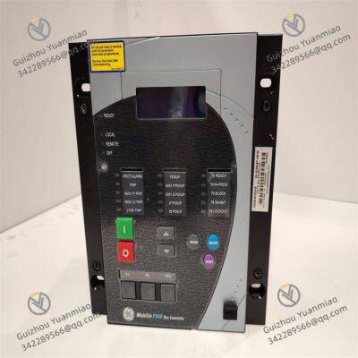
GE F650 F650BFBF2G0HIE is a powerful and widely used digital bay controller, belonging to the GE Multilin series of products. It plays a crucial role in fields such as power systems and industrial automation, providing reliable guarantees for the stable operation and precise control of various electrical equipment.
With advanced design concepts and exquisite manufacturing processes, this product can realize comprehensive protection, efficient control, and automated management of electrical systems. Whether it is ensuring the safe distribution of electricity in medium and low-voltage power distribution systems or coordinating the operation of various equipment in complex industrial automation production lines, the F650 F650BFBF2G0HIE demonstrates excellent performance and adaptability, and is a key component in modern industrial electrical control systems.

II. Technical Parameters
Communication Interfaces:
Equipped with rich communication interface configurations, such as an Ethernet communication board with 10/100Base TX, facilitating high-speed and stable data transmission with upper computers, other intelligent devices, or control systems. It supports multiple network protocols such as TCP/IP, meeting the needs of remote monitoring and centralized management.
It may also be equipped with redundant RS485 communication interfaces for connecting some traditional serial communication devices, ensuring communication reliability and compatibility, and supporting common serial communication protocols such as Modbus RTU.
I/O Interfaces: The I/O board configured in a specific slot has strong signal processing capabilities, with 8 digital input channels that can be used to access various switching signals, such as equipment operation status feedback and sensor trigger signals; 8 digital output channels can output control signals to drive executive components such as relays and contactors. In addition, it is equipped with 2 trip/close circuit monitoring circuits to monitor the on-off status of the circuits in real-time, providing important guarantees for the safe operation of the power system.
Auxiliary Voltage: It can adapt to a wide range of auxiliary voltages, and can work stably under 110 - 250 VDC (range 88 – 300 V) and 120 - 230 VAC (range 96 – 250 V). This enables it to operate reliably in different power environments, reducing usage restrictions caused by voltage fluctuations or different power supply specifications.
Parameters Related to Protection Functions:
In terms of overcurrent protection, it can quickly respond to and accurately detect overcurrent faults, and different overcurrent thresholds and action times can be set to adapt to different load characteristics and protection requirements.
Ground fault protection has high sensitivity, which can promptly detect ground faults, effectively preventing electrical accidents caused by grounding problems, and protecting personnel and equipment safety.
Voltage protection can monitor the system voltage in real-time, and act quickly when the voltage is abnormal, such as overvoltage and undervoltage, to avoid damage to electrical equipment due to voltage abnormalities.
Communication Protocols: It supports multiple mainstream industrial communication protocols, such as Modbus RTU, TCP/IP, DNP 3.0 level 2, and IEC 60870 - 5 - 104. The support of these protocols enables the F650 F650BFBF2G0HIE to seamlessly communicate and integrate with equipment and systems from different manufacturers, greatly improving the compatibility and scalability of the system.

III. Functional Features
Comprehensive Protection Functions:
It has high-speed and accurate fault detection capabilities, which can quickly identify various abnormal electrical states such as overcurrent, short circuit, and ground fault. Once a fault is detected, it immediately triggers corresponding protection actions, such as trip protection, to quickly cut off the faulty circuit, prevent the expansion of the fault range, effectively protect electrical equipment from damage, and ensure the safe and stable operation of the power system.
It provides multiple protection curves, including standard curves such as IEEE, IEC, ANSI, and I2t. Users can flexibly select appropriate protection curves according to actual application scenarios and the characteristics of electrical equipment to achieve personalized and precise protection configuration.
Efficient Control Functions: It can fully control the equipment in the electrical system, for example, realizing intelligent management of feeders, and automatically controlling the on and off of the circuit according to the system operation status and preset logic. At the same time, it supports remote control operations, facilitating operators to control equipment in real-time in the remote monitoring center, improving the convenience and timeliness of operations.
Flexible Automation Functions: It has a high degree of customizability, allowing users to flexibly set protection and control strategies according to specific application needs. By writing custom logic programs, complex automated control processes can be realized to meet diverse control requirements in different industrial scenarios, effectively improving production efficiency and the intelligence level of the system.
Good Communication Capabilities: With rich communication interfaces and support for multiple communication protocols, it can be easily integrated into various automation systems. It can perform real-time data interaction with upper computers, other intelligent devices, or control systems, upload data such as equipment operation status and fault information, and receive control commands at the same time, realizing centralized monitoring and collaborative work of the system, and facilitating efficient system management and maintenance.
User-Friendly Interface: Equipped with an intuitive graphic display screen, using standard symbols for display, it is convenient for operators to quickly understand the equipment's operation status and parameter information. The operation interface is simple and clear, and various control buttons are reasonably arranged, so even non-professionals can quickly get started to set up, debug, and perform daily operations on the equipment.

IV. Common Faults and Solutions
Communication Faults
Fault Phenomenon: The equipment cannot communicate normally with the upper computer or other equipment, with data transmission interrupted, lost, or incorrect.
Possible Causes: Loose or damaged communication line connections, such as network cables and RS485 communication lines; hardware faults of communication interfaces; incorrect communication protocol settings, including incorrect configuration of parameters such as IP address, port number, baud rate, and communication protocol type; existence of interference sources in the network, affecting communication quality.
Solutions: First, check the communication line connections to ensure that the line plugs are tightly inserted without looseness or disconnection. If necessary, replace the communication lines for testing. Then, check the communication interface hardware, which can be judged by the equipment's own diagnostic tools or replacement method. If damaged, it needs to be replaced in time. Carefully check and verify the communication protocol parameter settings to keep them consistent with those of the communicating counterpart equipment. For network interference problems, measures such as adding shielding, optimizing wiring, and using anti-interference equipment can be taken to reduce the impact of interference on communication.
Protection Misoperation
Fault Phenomenon: During the normal operation of the system, the protection functions of the equipment are accidentally triggered, such as overcurrent protection and ground fault protection actions, leading to unnecessary trips.
Possible Causes: Unreasonable setting of protection parameters, such as too low overcurrent threshold and too short action time; faults of measuring components such as current and voltage transformers, resulting in inaccurate measurement data and causing false protection judgment; the equipment is affected by external strong electromagnetic interference, which affects the normal judgment of the protection logic.
Solutions: Recheck and adjust the protection parameters. According to the load characteristics and operation requirements of the actual electrical equipment, reasonably set the protection threshold and action time. The accuracy of the parameters can be verified through simulated fault tests. Detect and calibrate measuring components such as current and voltage transformers, use professional testing equipment to check their measurement accuracy, and replace them in time if there is a fault. For electromagnetic interference problems, strengthen the shielding measures of the equipment, improve grounding conditions, stay away from strong electromagnetic interference sources, and install electromagnetic interference filters if necessary.
I/O Interface Faults
Fault Phenomenon: No response from digital input, unable to correctly detect external switching signals; digital output cannot normally drive executive components, such as relays not operating; the data collected by analog input is inaccurate, with a large deviation from the actual value.
Possible Causes: Open circuit, short circuit, or poor contact of the connection line between the I/O interface and external equipment; hardware fault of the I/O interface board; faults of external equipment, such as damaged sensors and faulty executive components.
Solutions: Check the connection line between the I/O interface and external equipment, use a multimeter to measure the on-off status of the line, and repair or replace the problematic line. If the line is normal, try to use the spare I/O interface channel for testing to determine if it is a hardware fault of the interface board. If the hardware is damaged, contact professional maintenance personnel to replace the interface board. For external equipment faults, check sensors, executive components, etc. one by one, and use the replacement method to determine the faulty equipment and replace it.
Equipment Crash or Unresponsiveness
Fault Phenomenon: The equipment suddenly stops working, the display screen has no display, and there is no response to any operation.
Possible Causes: Error in the internal software operation of the equipment, resulting in a crash; hardware overheating, causing automatic protection of the equipment; power supply fault, unstable or interrupted power supply.
Solutions: First, try to power off and restart the equipment, wait for a few seconds and then power it on again to see if the equipment can return to normal operation. If there is still no response after restarting, check the heat dissipation of the equipment, clean the dust on the surface and inside of the equipment, ensure the heat dissipation channel is unobstructed, and auxiliary cooling equipment such as cooling fans can be installed. At the same time, use a multimeter to check if the power supply voltage is normal and if the power interface is firm. If there is a problem with the power supply, repair or replace the power module in time. If the problem persists, there may be serious faults in the internal software or hardware of the equipment, and it is necessary to contact GE technical support personnel for further diagnosis and maintenance.


EMERSON 1C31113G01 Analog Input Module
EMERSON 5X00790G01 Compact Controller
EMERSON 5X00453G01 Power Supply Module
EMERSON 5X00846G01 8 Channel Analog Input Module
ABB PPD513A-23-111615 magnetic excitation controller
TRICONEX Safety Instrumented System (SIS) 4351B control module
Bentley Nevada 3500/22M Transient data interface module
Bently Nevada 3500/15-05-05-00 power module
Triconex 3009 processor module
ABB GFD563A102 3BHE046836R0102 Excitation Convection Interface Module
ABB PPD117A3011 3BHE030410R3011 Excitation Controller
ABB PCD231B101 3BHE025541R0101 Excitation Unit Controller
 yezi
Hi there! Welcome to my shop. Let me know if you have any questions.


