Product Description
I. Product Overview
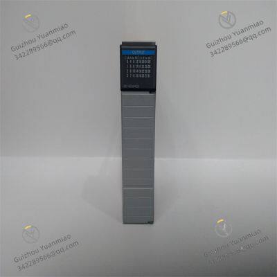
1746-OB32 is a 16-channel digital output module in Rockwell Automation's SLC 500 series, specially designed for the switch control of DC-type actuators in industrial automation control systems. It can convert the digital control signals of PLC into DC switching output to drive DC contactors, solenoid valves, DC motor drivers, indicator lights and other equipment. It is widely used in industrial scenarios dominated by DC equipment, such as electronic manufacturing, medical device production, warehouse automation, and water treatment. By stably and quickly executing control instructions to achieve precise control of equipment, it is an important executive component to ensure the efficient operation of automated production lines.

II. Functional Features
16-channel independent control: Equipped with 16 independent digital output channels, it can simultaneously perform switch control on 16 different DC actuators. It is suitable for scenarios that require centralized management of multiple DC devices, such as multiple sets of pushing cylinders on automated sorting lines and multiple DC-driven tooling on electronic assembly lines. This reduces the number of modules used and optimizes the system structure.
DC output adaptability: It supports DC voltage output (commonly 24V DC) and can directly drive various DC-type actuators without additional DC conversion devices, reducing system complexity and improving the stability of the control link. It is especially suitable for industrial sites with a large number of DC-powered equipment.
Stable load driving capability: Each channel has stable load-carrying capacity, and usually the maximum current per channel can reach 1.0A (resistive load), which can meet the power supply needs of most DC contactors, solenoid valves and other equipment, ensuring reliable operation of actuators and avoiding slow response or failure of equipment due to insufficient driving capability.
Clear status indication: Each output channel is equipped with an independent LED status indicator. When the channel outputs a signal, the indicator lights up, allowing operators to intuitively judge the working status of each channel. This facilitates function verification during system debugging and fault troubleshooting during daily operation, and quickly locates abnormal channels and corresponding equipment.
Reliable protection mechanism: Some models have built-in overcurrent protection function. When an overload or short-circuit occurs in the output channel, it can quickly cut off the output of that channel to prevent module damage and fault spread to the entire system. After the fault is eliminated, it can resume normal operation, improving the safety and durability of the system.
Seamless system integration: As a standard module of the SLC 500 series, it has excellent compatibility with the rack, power module and CPU module of the series. It can be directly installed on a standard rack, realizes high-speed data interaction with the CPU module through the backplane bus, and supports programming software such as RSLogix 500 for configuration and program writing, facilitating the rapid construction and expansion of the system.
Industrial-grade environment adaptation: Adopting industrial-grade design standards, it has strong anti-electromagnetic interference capability. It can operate stably in the working temperature range of 0℃-60℃ and relative humidity of 5%-95% (non-condensing), and can withstand the impact of vibration, shock, etc. in industrial sites, ensuring long-term reliable operation.

III. Technical Parameters
Output parameters:
Number of output channels: 16 channels, independent output.
Output signal type: Digital switching signal (on/off).
Output voltage range: 24V DC (typical value, subject to specific model).
Maximum current per channel: 1.0A (resistive load), derating is required for inductive loads.
Maximum total current: The total current of the module does not exceed 10A to prevent overload of the main power supply.
Response time: The output state switching responds quickly, usually at the millisecond level, ensuring quick response to control instructions and timely action of equipment.
Electrical parameters:
Backplane current: Approximately 40mA at 5V DC (specific value varies slightly by model), imposing little burden on the system power supply.
Isolation method: Photoelectric isolation is adopted between channels and between channels and the backplane, with an isolation voltage usually of 1500V AC, effectively blocking electrical interference and preventing fault spread.
Physical parameters:
Dimensions: Approximately 160mm in length, 100mm in width, 150mm in height (compatible with other modules in the SLC 500 series), suitable for installation in standard racks, saving installation space.
Weight: Approximately 0.6kg, light in weight, easy to install and carry.
Environmental parameters:
Operating temperature: 0℃-60℃.
Storage temperature: -40℃-85℃.
Relative humidity: 5%-95% (non-condensing).
Anti-vibration performance: 10-55Hz, amplitude 0.38mm.
Impact resistance: Peak acceleration 15g (duration 11ms).

IV. Working Principle
Instruction reception: 1746-OB32 receives digital control instructions from the PLC CPU module through the backplane bus of the SLC 500 series. These instructions are transmitted in binary form, and each bit corresponds to the state of an output channel (1 indicates valid output, 0 indicates invalid output).
Signal conversion and driving: After receiving the control instructions, the drive circuit inside the module controls the output switching devices (such as transistors or relays) of the corresponding channels to turn on or off according to the instruction state. For DC output channels, when turned on, the DC power supply voltage (such as 24V DC) is applied to the external actuator to make it start or act; when turned off, the power supply is cut off, and the actuator stops working.
Status feedback: The module monitors the working status of each output channel in real time and feeds back the status information to the CPU module through the backplane bus to ensure that the CPU can grasp the execution situation in real time. At the same time, the LED indicator of each channel lights up or goes off according to the actual output state, providing intuitive visual status reference for on-site operators.
Protection mechanism response: If an overload or short-circuit fault occurs in a certain channel, the overcurrent protection circuit of the module responds immediately, cutting off the output of that channel to avoid damage to internal components of the module and prevent the fault from affecting other channels. At this time, the indicator of the corresponding channel may indicate the fault in a specific way (such as flashing), and at the same time, the fault information is fed back to the CPU module. The CPU can trigger an alarm (such as sound and light alarm) or execute emergency shutdown and other protection measures according to the preset program.
System collaborative operation: In the automation system, 1746-OB32, as the core component of the execution layer, works together with the logic control of the CPU module and the signal acquisition of the input module to form a complete control closed loop. For example, in a medical device production line, when the input module detects a workpiece in-place signal, the CPU module issues a control instruction after logical judgment. The corresponding channel of 1746-OB32 outputs a DC signal to drive the DC welding tooling to complete the welding process. Then the module feeds back the action completion status to the CPU, entering the next working cycle to ensure the orderly progress of the production process.


ABB PPD513A-23-111615 magnetic excitation controller
TRICONEX Safety Instrumented System (SIS) 4351B control module
Bentley Nevada 3500/22M Transient data interface module
Bently Nevada 3500/15-05-05-00 power module
Triconex 3009 processor module
ABB GFD563A102 3BHE046836R0102 Excitation Convection Interface Module
ABB PPD117A3011 3BHE030410R3011 Excitation Controller
ABB PCD231B101 3BHE025541R0101 Excitation Unit Controller
ABB 5SHY3545L0010 3BHE009681R0101 High-Voltage Thyristor Module
ABB PCD230A 3BHE022291R0101 Controller Module
ABB 5SHY3545L0009 3BHB013085R0001 IGBT Module
Bently Nevada 3500/25 enhanced key phase module
 yezi
Hi there! Welcome to my shop. Let me know if you have any questions.


