Product Description
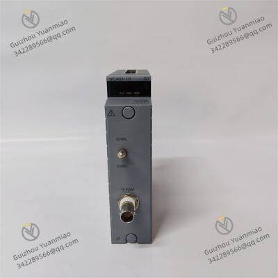
Yokogawa VC401-10
I. Overview
The Yokogawa VC401-10 is an industrial automation control module launched by Yokogawa, serving as one of the core components of the Centum CS/VP control system. This module is primarily used for generating and controlling analog output signals, supporting the conversion of digital signals into standard industrial analog quantities (such as current and voltage), and driving actuators (e.g., valves, frequency converters) to achieve precise process control. Designed with a focus on high reliability, high precision, and anti-interference capabilities, it is suitable for complex industrial scenarios in petroleum, chemical, power, and other industries.
II. Functional FeaturesMulti-Signal Type Output
Supports standard analog output: 4-20mA current signals, 1-5V DC voltage signals, etc., adapting to various actuators.
Can be configured with linear or non-linear output characteristics to meet special process requirements (e.g., non-linear compensation for valve opening).
High Precision and Stability
Output accuracy reaches ±0.05% FS (full scale), with 16-bit digital-to-analog conversion (DAC) to ensure the accuracy of control signals.
Built-in hardware filtering and software calibration functions suppress temperature drift and external interference, ensuring stable long-term operation.
Rich Communication and Control Interfaces
Supports real-time communication with controllers via Yokogawa's internal bus (such as the HW bus) to receive control commands and status feedback.
Equipped with a fault diagnosis interface, enabling real-time monitoring of module status (e.g., output anomalies, open circuit alarms) through system software.
High-Reliability Design
Electrical isolation: Optocoupler or transformer isolation is adopted between the input and output sides, with an isolation voltage ≥500V DC to prevent ground loop interference.
Redundancy function: Supports hardware redundancy configuration (such as dual-module hot standby), enabling automatic switching during faults to ensure uninterrupted system operation.
Protection level: Meets industrial environment requirements, resisting vibration, dust, and electromagnetic interference (EMI).
Flexible Configuration and Maintenance
Output range and fault-safe modes (such as maintaining the current value or outputting a safe value) can be configured online through dedicated software (e.g., Centum CS3000).
Supports hot-swapping, eliminating the need for shutdown during maintenance and improving system availability.

III. Technical Parameters
| Parameter Category | Specific Indicators |
|---|
| Input signal | Digital signals (binary commands from the controller, such as 16-bit data) |
| Output signal types | Current: 4-20mA, 0-20mA; Voltage: 1-5V DC, 0-10V DC |
| Output accuracy | ±0.05% FS (at 25°C), temperature drift ≤±0.005% FS/°C |
| Resolution | 16 bits (1/65536) |
| Update rate | Typical value ≤5ms (depending on bus communication speed) |
| Power supply | 24V DC ±10%, power consumption ≤5W |
| Operating temperature | -20°C to +60°C, storage temperature: -40°C to +80°C |
| Dimensions | Approximately 100mm × 100mm × 50mm |
| Protection level | IP54 (dust and water spray protection) |
| Isolation characteristics | Three-way isolation of input-output-power, isolation voltage 500V DC (1 minute) |
IV. Working Principle
The working principle of the VC401-10 revolves around four core links: "digital command reception-signal conversion-power drive-safe output", achieving precise control through the collaboration of hardware circuits and software logic.
1. Digital Signal Reception and Processing
Command acquisition: The module receives digital control commands (such as 16-bit binary data) from the controller via the internal bus (e.g., HW bus). The commands include target output values (such as digital codes corresponding to 4-20mA) and functional parameters (such as range and fault mode).
Data parsing: The built-in microprocessor (MCU) parses digital commands, performs verification (such as CRC check) and format conversion to ensure data accuracy.
2. Digital-to-Analog Conversion (D/A Conversion) and Signal Conditioning
D/A conversion: A 16-bit high-precision digital-to-analog converter (DAC) converts digital codes into analog voltage signals (e.g., 0-5V DC), with conversion accuracy guaranteed by a reference voltage source (such as a high-precision voltage reference chip).
Signal conditioning:
Amplification: Power amplification of low-voltage signals to meet output driving capability (e.g., driving a 250Ω load for 4-20mA output).
Filtering: RC filters eliminate high-frequency noise to ensure smooth analog signals.
Linearization correction: If the output characteristic is non-linear (such as the temperature compensation curve of a thermocouple), correction is performed through software algorithms or hardware circuits.

3. Analog Output and Drive
Current/voltage conversion: Convert voltage signals to standard current or voltage outputs according to configurations:
Current output: Convert voltage signals to 4-20mA current through a constant current source circuit (such as an operational amplifier + power transistor) to ensure current stability during load changes.
Voltage output: Driven by a buffer amplifier to maintain output voltage stability during load changes (e.g., load capacity ≥1kΩ).
Load matching: The output circuit features impedance matching design to avoid signal distortion or module damage due to abnormal loads (such as short circuits or open circuits).
4. Electrical Isolation and Safety Protection
Isolation design: Electrical isolation between the input side (digital signals) and output side (analog signals) is achieved through optocouplers or transformers, cutting off ground loops to prevent external interference (such as frequency converter harmonics) from affecting control signals, while protecting the controller from on-site faults (such as overvoltage).
Multiple protection mechanisms:
Overcurrent/overvoltage protection: If a short circuit or overvoltage occurs at the output, the protection circuit (such as current limiting resistors, TVS diodes) acts quickly to limit current/voltage within a safe range, avoiding damage to the DAC and drive components.
Open circuit detection: For current output scenarios, the module can detect load open circuits and output fault signals according to configurations (such as maintaining the last value or switching to a safe value).
Thermal protection: An internal temperature sensor monitors the chip temperature, triggering an alarm and limiting output when overheated to prevent component overheating failure.
5. Status Feedback and Redundancy Control
Feedback mechanism: The module samples output signals in real time, compares them with target values, triggers self-diagnosis if the deviation exceeds the threshold (such as ±0.1% FS), and sends fault information (such as "output anomaly") to the controller via the bus.
Redundancy function (if configured): In dual-module redundancy, the main module and slave module synchronize data in real time. When the main module fails, the slave module automatically takes over output, with a switching time ≤10ms to ensure control continuity.
6. Power Supply and Clock Synchronization
Power management: The 24V DC input is converted into voltages required by each chip (such as 5V, 3.3V) through internal DC-DC conversion. Filter capacitors and voltage regulators reduce ripple to ensure stable operation of the DAC and processor.
Clock synchronization: The internal clock provides a timing reference for DAC conversion and data processing, supporting synchronization with the system bus clock to ensure the time consistency of outputs from multiple modules (such as coordinated actions of multiple actuators in complex control systems).
V. Common Faults and Solutions
| Fault Phenomenon | Possible Causes | Solutions |
|---|
| Abnormal output signal (e.g., out of range, jumps) | 1. Digital command transmission error (bus interference)
2. DAC chip failure
3. Loose wiring in the output circuit | 1. Check bus cable shielding and grounding, restart the module
2. Replace the module or DAC chip
3. Tighten wiring and check terminal block contact |
| No output or fixed output value | 1. Power failure (insufficient voltage)
2. Short circuit/open circuit in the output circuit
3. Module configuration error (e.g., range not activated) | 1. Measure power voltage and check the power supply circuit
2. Use a multimeter to detect output circuit resistance and eliminate short circuits/open circuits
3. Reconfigure the range and output mode through software |
| Isolation fault alarm | 1. Aging of isolation components (optocoupler/transformer)
2. Isolation breakdown caused by external strong interference | 1. Replace the module
2. Strengthen on-site wiring shielding and keep away from interference sources (such as motors, frequency converters) |
| Temperature alarm | 1. Excessive ambient temperature
2. Blocked module cooling holes
3. Abnormal heating of internal components | 1. Improve the ventilation environment and install a cooling fan
2. Clean the module surface dust
3. Detect internal chip temperature and replace the module if necessary |
| Redundancy switching failure | 1. Communication interruption between master and slave modules
2. Incorrect redundancy configuration parameters
3. Hardware failure of the master module | 1. Check redundancy bus connection and restart the module
2. Reconfigure redundancy parameters (such as address, synchronization period)
3. Replace the master module |
VI. Conclusion
As a key execution module in industrial automation systems, the Yokogawa VC401-10 achieves reliable conversion from digital control commands to analog outputs through high-precision digital-to-analog conversion, electrical isolation, and multiple protection designs. Its working principle runs through the entire process of signal processing, and troubleshooting common faults requires a combination of hardware detection and software configuration to ensure the stable operation of industrial control systems. In practical applications, regular module calibration and status monitoring are recommended to enhance system reliability and control accuracy.


ABB REM620 MOTOR PROTECTION CONTROL RELAY
Cameron AAP3798102-00130 Operation Panel
ABB RTA Board PU512V2 3BUR001401R1 Real Time Accelerator Module
TRICONEX 3451 Safety Controller
ABB RTA Board PU515A 3BSE032401R1 eal Time Accelerator Module
ABSOLUTE MOX12-P3509 Power Module
TRICONEX 3564 single-channel digital input module
Kollmorgen AKM22E-ANB2R-00 Servo Motor
ABB KUC711 digital input module
ACQUISITIONLOGIC AL81G High-Performance Data Acquisition Module
TRICONEX 3624 Supervised Digital Output (SDO) module
ALPHA SP060S-MF2-20-1C1-2S Planetary Gearbox
ICS Triplex 9300-9832 Analog input TA module
ICS Triplex 9300-9852 Digital Output Module
ICS Triplex 9852-9802 Digital Output Module
ICS Triplex T8110B Programmable Logic Controller
ICS Triplex T8151B Triple Redundancy (TMR) Programmable Logic Controller (PLC)
Yokogawa ANB10D-425/CU2N ESB Bus Node Unit
 yezi
Welcome to my shop, I'm glad to serve you. Please feel free to send me any questions you may have.


