Product Description
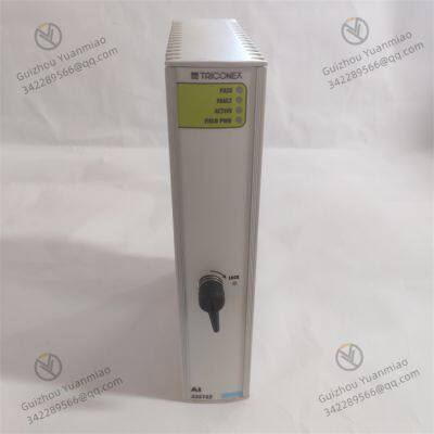
TRICONEX Series Module -2
The TRICONEX AI3351S2 is a core analog input module of the TRICONEX Safety Instrumented System (SIS) under Rockwell Automation. Positioned as an "industrial-grade high-safety analog signal acquisition unit", it is specifically designed for critical industries involving safety interlocks such as petrochemicals, oil and gas extraction, and fine chemicals. It undertakes the core function of "accurate acquisition and real-time transmission of analog signals under hazardous operating conditions".
Its design integrates three core features: "safety redundancy", "wide-range signal compatibility", and "fault self-diagnosis". As a key signal access carrier for the TRICONEX system to achieve "integrated safety control and risk early warning", it is widely compatible with the TRICON 3000/4000/5000 series safety controllers and meets the requirements of Safety Integrity Level 3 (SIL 3).

Basic Information and Product Positioning1. Interpretation of Model and Product Series
The model naming of TRICONEX safety modules follows the logic of "function identifier + signal type + hardware specification". The meaning breakdown and product attribution of AI3351S2 are as follows:
Meaning of the Model:
"AI": Function code, which stands for "Analog Input". It clearly defines the core function of the module as collecting analog signals, distinguishing it from "DI (Digital Input)", "DO (Digital Output)", and "AO (Analog Output)" modules.
"3351": Series number, representing the third-generation analog input module platform of TRICONEX. It has optimized signal sampling accuracy, anti-interference capability, and redundancy compatibility. Compared with the previous-generation AI3301 module, its sampling rate is increased by 30%, and it supports expanded signal types.
"S2": Hardware version and safety level identifier. The "S" stands for "Safety", indicating that the module is compatible with SIL 3 safety loops. The "2" represents the second-generation hardware version, which has optimized power management and diagnostic algorithms, and is compatible with TRICONEX system firmware V11.3 and above.
Product Attribution:
It belongs to the TRICONEX Safety Instrumented System (SIS) product line and serves as the "analog signal entry point" for TRICON controllers. It must be used in conjunction with TRICON 3000/4000/5000 series controllers (such as the TRICON 5130) and cannot operate independently. It is mainly used to collect continuous analog signals output by on-site sensors (e.g., pressure, temperature, and liquid level sensors) and provide raw data support for safety interlock logic.
2. Physical and Installation Characteristics
As the "analog signal acquisition terminal" of the TRICONEX system, the physical design of the AI3351S2 is strictly compatible with the standard TRICON rack, ensuring installation compatibility and meeting the requirements of safety redundancy deployment. Its external dimensions are 267mm (length) × 102mm (width) × 38mm (height), and it is a TRICONEX "dual-slot standard module". It occupies 2 adjacent slots in the TRICON rack (with a slot spacing of 31mm) and can be installed symmetrically with another AI3351S2 module of the same model to form a "1+1" redundancy architecture. The module weighs approximately 0.65kg and consists of a stainless steel housing, a multi-layer PCB board, a signal isolation circuit, and a status indicator light assembly. The housing is made of 304 stainless steel with a surface passivation treatment, featuring corrosion resistance and impact resistance, which enables it to adapt to the oily and highly corrosive environment of chemical industry sites.
The installation method adopts a guide rail locking design. The bottom of the module is equipped with a guide rail, which can be accurately fitted with the rack guide rail. Both sides are provided with spring-loaded locking bolts to prevent loosening after installation. At the same time, it supports "hot swapping" (in compliance with the IEC 61326-3-2 industrial safety standard), so there is no need to shut down the controller during maintenance, meeting the core requirement of "non-stop maintenance" for safety systems. On the left side of the front panel, there are 6 LED indicator lights arranged vertically, with clear color coding for easy on-site inspection:
Power status light (PWR): Green indicates normal power supply, red indicates power failure, and yellow indicates standby power switching.
Operation status light (RUN): Green indicates normal signal acquisition, blinking green indicates signal calibration in progress, and red indicates module failure.
Redundancy status light (RED): Green indicates normal redundancy synchronization, yellow indicates redundancy switching in progress, and red indicates redundancy failure.
There are also 4 channel status lights (CH1~CH4): Green indicates normal single-channel acquisition, and red indicates channel failure (e.g., signal over-range).
The rear panel adopts a combined design of "Phoenix terminals + redundancy interface", which prevents incorrect insertion and facilitates wiring:
The signal input end is equipped with 16 Phoenix terminals (divided into 4 groups, 4 channels per group, supporting differential input), which can be adapted to 2-wire or 4-wire sensors.
The power supply end is provided with 2 24V DC input terminals (with reverse connection protection and supporting redundant power supply).
The redundancy synchronization interface is a 1-channel RJ45, used for data synchronization with redundant modules, with a communication rate of 100Mbps.
There is also a 1-channel USB Type-C calibration interface, which can be directly connected to calibration equipment for on-site signal calibration without disassembling the module.

Core Technical Parameters

Application Scenarios and Typical Cases1. Petrochemical Industry (Safety Interlock System for Catalytic Cracking Units)
Core Requirements: Catalytic cracking units are key equipment in petrochemical plants, requiring collection of analog signals such as reactor temperature (4 groups of thermocouples, measuring range 0~800℃), regenerator pressure (4 pressure sensors, 4~20mA), and feed oil flow (2 flow sensors, 0~5V). When temperature exceeds 700℃ or pressure exceeds 0.8MPa, an emergency shutdown (ESD) must be triggered. Signal acquisition must be delay-free and error-free, with the module capable of adapting to high-temperature, oily environments.
Application Solution:
Each catalytic cracking unit is configured with 2 TRICON 5130 controllers, each paired with 2 AI3351S2 modules (1+1 redundancy). The 16 channels collect signals from 8 key sensors (each sensor with 2-channel cross-validation) to ensure acquisition accuracy.
Modules transmit data to controllers via TRICON's proprietary bus. Controllers execute interlock logic and immediately trigger ESD actions upon detecting parameter overruns. Real-time data is simultaneously uploaded to the MES system via OPC UA protocol for production process monitoring.
Benefiting from AI3351S2's wide temperature design and corrosion-resistant housing, modules can be directly installed in cabinets near the unit without additional temperature and moisture control measures, reducing deployment costs.
2. Oil and Gas Extraction Industry (Wellhead Pressure Monitoring System)
Core Requirements: Oil and gas wellheads require real-time collection of wellhead pressure (6 pressure sensors, 4~20mA) and pipeline temperature (4 RTD sensors, PT100). When pressure exceeds 10MPa or temperature exceeds 120℃, wellhead valves must close. The module must adapt to harsh "high-temperature, vibrating, dusty" wellhead environments and support redundant deployment to prevent signal interruptions.
Application Solution:
Each wellhead is equipped with 1 TRICON 4100 controller and 2 AI3351S2 modules (redundant configuration). The 16 channels cover 10 monitoring points (including 2 standby channels). Modules feature IP65 front panel protection to resist wellhead dust and water spray.
The module's built-in vibration resistance design (compliant with IEC 60068-2-6 standard) withstands mechanical vibrations during wellhead extraction, preventing data fluctuations. Data is transmitted to the local wellhead HMI via Modbus RTU protocol for real-time viewing by on-site personnel.
Redundant modules achieve synchronization cycles ≤1ms. Even if the main module fails due to environmental interference, the backup module switches seamlessly, ensuring uninterrupted pressure monitoring and preventing safety accidents from wellhead overpressure.
3. Power Industry (Boiler Water Level Safety Control System)
Core Requirements: Thermal power plant boilers require collection of drum water level (3 differential pressure sensors, 4~20mA), feed water flow (2 flow sensors, 0~10V), and furnace temperature (3 thermocouples, Type K). When water level drops below 100mm or rises above 800mm, feed pump speed must be adjusted or furnace shutdown triggered. The module requires high sampling accuracy and strong anti-electromagnetic interference capability (power plants have strong electromagnetic environments).
Application Solution:
The boiler control system is configured with 1 TRICON 5000 controller and 1 AI3351S2 module. 10 of the 16 channels collect key parameters (including 3 redundant water level signal acquisitions), with the remaining 6 channels as standby.
The module utilizes 24-bit Delta-Sigma ADC and differential input design with common-mode rejection ratio ≥100dB, enabling it to resist electromagnetic interference from power plant generators and transformers while ensuring water level signal acquisition accuracy.
 Application Scenarios and Typical Cases1. Petrochemical Industry (Safety Interlock System for Catalytic Cracking Units)

Bently 330103-05-30-10-02-00 Proximity Transducer
Bently 330101-00-20-05-02-05 Proximity Transducer
Bently 330104-00-05-05-01-05 Proximity Transducer
ENTERASYS A2H254-16-RH Ethernet Switch
FOXBORO/ENTERASYS A2H254-16-RH Ethernet Switch
TRICONEX RO3451 Digital Input Module
ASML MC1AB37 4022.437.1856 Motor Controller
TOKYO ELECTRON TEB207-12 OGSI EC80-000157-12 Electronic Module
Eaton CS-TX3-3. 81X2.54-64TW Pluggable Terminal Block
REXROTH VT-HNC100-1-23/M-08-P-0 Digital Axis Control
Woodward 8237-1369 ProTech-GII Overspeed Protection Panel
ABB XVC768116 3BHB007211R116 Control Inverter
ABB 560PSU02 1KGT011900R0001 Power Supply Unit Module
GE IS420PPNGH1A Controller Gateway Module
GE UCSC H1 IS420UCSCH1A-F.V0.1-A UCSC Controller
ALSTOM STO1726KO1 Safety Torque Off (STO) Module
ALSTOM I/OBE2 12004-104-00 V1.0.0 Safety I/O Module
ALSTOM I/OBUS2 12004-103-01 VER:V1.20 I/O Bus Expansion Board
 yezi
Hi there! Welcome to my shop. Let me know if you have any questions.


