Common Mode Choke Insights & Buyer's Guide
Boost your performance metrics with ease with a Common Mode Choke, the low-cost and easy-to-install white hack for signal interference as well as electromagnetic noise management. Whether you’re an enthusiast or a seasoned professional, our kit has everything you need to eliminate EMI challenges in your projects successfully. Uncover how common mode chokes can help in achieving better circuit performance through noise reduction and signal clarity maximization
What is a Common Mode Choke and How Does it Work?
Elucidating The Principle of Functioning of Common Mode Chokes
Common mode filters are a type of inductor designed to eliminate common mode noise in a given electrical circuit. These filters operate by restricting the flow of common mode currents while permitting the flow of differential mode currents. The principle is based on the fact that common mode noise, which usually affects both legs of a given cable, can be drastically reduced if impedance is applied to such unwanted signals. Coarse coil windings establish the impedance in question over a core which results in magnetic flux that counteracts common mode currents. As a consequence, the noise gets reduced.
The Differences Between Common Mode Chokes and Differential Mode Chokes
Even if both common mode and differential mode chokes filter out noise, their intended purposes vary greatly. Common mode chokes filter out noise due to common mode currents, which is the EMI noise present on both lines of a circuit wire. On the other hand, differential mode chokes are more concerned with the noise present in-between the two lines. Knowing the difference is important in order to make a proper selection, as employing a common mode choke instead of a differential mode choke (or the other way around) would result in poor noise mitigation.
Primary Uses of Common Mode Chokes in Electronics
Common mode chokes have a wide variety of uses in the field of electronics. They are a necessary part of a power line filter for reducing noise produced on AC power lines. They also maintain integrity of the digital signals in USB and other data transmission cables. In antenna circuits and HF applications, common mode chokes act as filters to improve performance by reducing interference. The adaptability of these components is vital in consumer and industrial electronics.
How to Select the Right Common Mode Choke for Your Project?
Tips for Selecting the Correct Core Material for Best Functionality
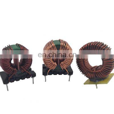
The core material used in a common mode choke significantly affects choke performance. Ferrites are common due to the fact that they have magnetic peripheral over a large range of frequencies. Certain applications benefit from the higher efficiency provided by toroidal cores due to their shape. Choosing a core material also depends on the project's requirements like demand for frequency and noise suppression level.
What Role Does Frequency and MHz Range Play In Selection?
Frequency is one of the most important factors in selection of a common mode choke as it highly determines the choke's effectiveness in noise attenuation . The majority of applications require chokes that work within specified MHz ranges. In the case of hf (high frequency) applications, it is preferable to work with chokes that have high impedance in the range of frequencies to be passed. Knowing the frequency requirements of a project is crucial for best performance and noise elimination.
How to Set the Correct Level of Impedance?
In the case of a common mode choke, choosing the device that is set at the lower limit of the impedance measurement is ideal to allow best noise attenuation through rule of lower resistance. The term impedance in ohms indicates the sidirectional flow of current across the choke. In terms of common mode impedance, the higher the level the better the reduction implies unwanted signals. It is crucial to tailor the impedance value to the requirements of the circuit for effective noise suppression as well as to prevent any adverse impact on the signal of interest.
Step-by-Step: Building a Common Mode Choke Using a DIY Kit
Basic Components and Tools Required for DIY Kits
Our toroidal and ferrite core common mode choke DIY kit comes with detailed instructions for each component of the kit and all the necessary components. This includes copper wire windings, ferrite and toroidal cores, and even detailed instructions. In addition, we provide a list of tools to be used which include measuring equipment and a winding jig. This will ensure precision and accuracy in your work. This approach will cultivate your technical skills, while providing you with a practical understanding of common mode chokes and how they function.
Guide to Winding Your Common Mode Choke
Our guide provides instructions for optimal bi-filar winding which is most effective in common mode chokes. This is a very crucial step in ensuring the common choke functions properly. By following the DIY guide, you achieve precision, step-by-step bifilar winding, and optimal magnetic flux control. The electromagnetic interference emitted by the common mode choke highly depends on magnetic flux control. This guide provides all the nuance needed for different bi-filar winding applications.
Inspecting and Measuring Your Built Choke’s Performance
Using the emission analyzers and impedance measurement devices available to you, ensure that the common choke you have assembled performs as seamless as expected. Verifying the noise reduction capabilities of the built common choke is an essential next step.Our DIY kit comes with complete testing instructions to verify your construction, confirming your choke is set up to mitigate interference for your applications.
Understanding the Impact of Core Types on Common Mode Choke Performance
Which Is Better: Toroidal or Ferrite Cores?
The selection of a core greatly affects the efficiency of a mode choke, and both cores have their strengths and weaknesses. For example, Toroidal cores maintain greater magnetic coupling and even containment of flux which further enhances performance, making them superior for high efficiency devices. Their versatility across frequencies, however, allows for ferrite cores to be useful for EMI suppression in a lot of contexts. Understanding the needs will lead to determination of the core type that will allow the most efficiency for the choke.
Signal Integrity and Core Isolation
A method to isolating signals in electronic circuits is maintaining core isolation. Adequate isolation enables the common choke to effectively filter out noise without affecting mode signals. With our DIY kit, you will learn about the best core isolation methods that you can do which allows your circuit to do its job without interference.
What Does Core Size In Centimeters Mean For Noise Attenuation?
The measurement of the core in centimeters influences the amount of noise that the choke can suppress. This is due to the fact that bigger cores feature more winding turns, which increases the amount of impedance that can be suppressed. But as was noted in previous sections, certain restrictions regarding project size will need to be considered. Being aware of these factors helps interface core size and EMI effieciency.
How to Effectively Use Common Mode Chokes to Eliminate Interference?
Common Sources of Noise and How Chokes Combat Them
Chokes of this type can silnen noise caused by circuit disruptions, electromagnetic and power line interferences, etc. They help eliminate interference by adding impedance to these unwanted signals, ensuring that your circuits operate without hitches. Our DIY kit provides insights on these noise sources and offers strategies for eliminating them comprehensively.
Strategies for Maximizing Attenuation and Reducing Interference
Attenuation and reduction of interference is derived from the optimal placement and installation of common mode chokes. Positioning your choke at the right location within the circuit can help significantly. Your performance may improve with winding changes as well as core material selection. Tips and strategies are provided in our kit to ensure optimal functioning of your common mode choke.
Tips on Proper Installation and Maintenance of Common Mode Chokes
To maintain peak performance, the common mode chokes need to be installed accurately. Along with installation instructions, our kit offers maintenance guidance designed to enhance the longevity and efficacy of your chokes over time. Regular impedance inspections coupled with proper tightening of the coil leads will enhance the operational life and efficiency of your noise suppression devices.
Frequently Asked Questions (FAQs)
Q: What are common types of common mode chokes?
A: Common types of common mode chokes include toroidal core chokes, bifilar windings chokes, and transformer-based chokes. Each type is designed for specific applications to mitigate interference and improve signal integrity.
Q: How does a common mode choke with bifilar windings work?
A: A common mode choke with bifilar windings functions by winding two wires closely together in opposite direction around a core, such as a toroid. This arrangement helps cancel out common mode noise while allowing differential mode signals to pass unimpeded.
Q: What is the role of a toroidal core in a common mode choke?
A: A toroidal core in a common mode choke helps to concentrate the magnetic field, enhance efficiency, and reduce electromagnetic interference (EMI). This design is particularly effective for high frequency applications.
Q: How does a common mode choke help with interference issues?
A: A common mode choke helps reduce interference issues by blocking high-frequency noise signals that travel along power and data lines. This prevents the noise from becoming part of the antenna system and reduces overall noise levels.
Q: Can a common mode choke fix high current interference problems?
A: Yes, a common mode choke can mitigate interference from high current sources by providing high differential mode impedance, which helps to suppress unwanted high frequency signals.
Q: What precautions should be taken when using a common mode choke?
A: When using a common mode choke, ensure proper insulation and consider the voltage and current ratings. It's also important to evaluate the antenna placement and make sure the choke does not adversely affect the signal output.


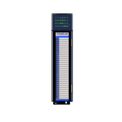 IC694BEM331LTC 1500 V Transient Common Mode Rejection/bus Controller ModuleUS$ 3588.00MOQ: 1 PalletI/O Number: IC694BEM331LTCPlace of Origin: AmericaCommunication Interface: ModubusProduct name: bus controller moduleXiamen Xiongba E-commerce Co., LTD
 1 Yr
1 Yr Common Mode Chokes ManufacturersNegotiableMOQ: 1000 UnitsPlace of Origin: Tamil Nadu, IndiaUsage: ElectronicPhase: ThreeCoil Structure: ToroidalSyrma Technology Private Limited
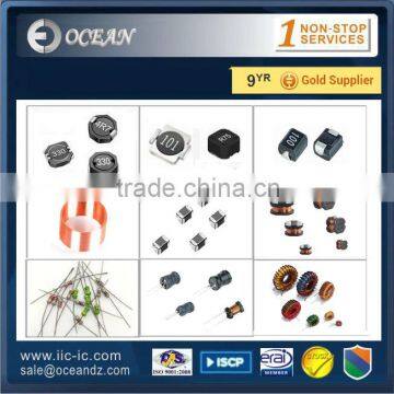 Common Mode Choke Coil InductorUS$ 0.01 - 1MOQ: 100 PiecesPlace of Origin: ChinaBrand Name: Well-knownModel Number: Inductor CoilOcean Technology Company Ltd.
 Smd Common Mode Choke,smd Air CoilUS$ 0.01 - 0.6MOQ: 1000 PiecesPlace of Origin: Guangdong, ChinaBrand Name: GE CoilModel Number: WS018Dongguan Golden Eagle Coil Co., Ltd.
 Automatic Big Toroid Common Mode Chokes Winding Machine(SS900B8 Series Final OD 20~150mm) Replace JOVIL Toroidal WinderNegotiableMOQ: 1 SetCondition: NewPlace of Origin: Fujian, ChinaBrand Name: SanShineModel Number: SS900B8Sanshine (Xiamen) Industrial And Trading Co., Ltd.
 Common Mode Filters for Automobile Signal Line ACT45B-510-2P-TLUS$ 0.1 - 10MOQ: 2000 PiecesPlace of Origin: ArubaBrand Name: originalModel Number: ACT45B-510-2P-TLShenzhen Xiongfengke Electronics Co., Ltd.
 is Set to Single Injection Mode,HY-CRI200 Common Rai Injector Testing MachineNegotiableMOQ: 1 SetType: Engine AnalyzerVoltage: 220V/380VPower: 5.5kwCertification: ISO9001:2008Taian Haiyu Machinery Co., Ltd.
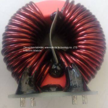 Nano-crystalline EMC Common Mode Choke CoresNegotiableMOQ: 1500 BoxesBrand Name: kai rui dePlace of Origin: ChinaUsage: OtherTheory: OtherZhengzhou Kairuider New Material Technology Co. LTD
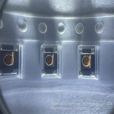 Common Mode Chokes / Filters ACT45B-101-2P-TL003US$ 0.8 - 1.5MOQ: 10 PiecesBrand Name: TDKPlace of Origin: ChinaModel Number: ACT45B-101-2P-TL003Shenzhen Kexinxin Technology Co., Ltd.
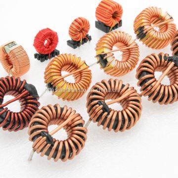 Toroidal Common Mode Choke Coil Power InductorsUS$ 0.10 - 1.84MOQ: 100 PiecesBrand Name: AL TRANSFOPlace of Origin: ChinaModel Number: AL-I51Al Transfo Design Group Ltd
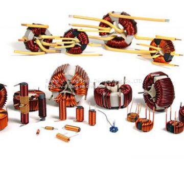 UU9.8/10.5/16 Power Filter Inductors PCB Common Mode Choke Coils, Audio Switch Transformer, ISO ULUS$ 0.5 - 5MOQ: 1000 PiecesBrand Name: V-YOUNGPlace of Origin: ChinaModel Number: uu inductorBeijing V-Young Tech. Development Co.,LTD
 Common Mode Chokes DLW5BTN102SQ2LUS$ 0.1 - 5MOQ: 10 PiecesD/C: NewestPackage: 2020Model Number: DLW5BTN102SQ2LType: Other, Common Mode ChokesShenzhen Shijibaike Electronic Co., Ltd.
 Common Mode ChokeNegotiableMOQ: 1 SetPlace of Origin: ChinaShenzhen Jingquanli Electronics Co., Ltd.


 Common Mode ChokeNegotiableMOQ: 50 SetsBrand Name: swibonPlace of Origin: ChinaModel Number: Common Mode ChokeDongguan Swibon Electronic Co., Ltd

 Nanocrystalline Common Mode ChokesNegotiableMOQ: 300 PiecesModel Number: common mode chokesType: Other, common mode chokesBrand Name: BIDRAGONPlace of Origin: Beijing, ChinaBeijing Double Dragon International Industrial & Mining Machinery Co., Ltd.
 Lead Purchaser requested a quote for Common mode filter2025-10-22 13:21:40
 Importer requested a quote for hot sale Toroidal ferrite common mode choke coil/ inductor coil
Quality Choice2025-10-19 14:38:10
Importer requested a quote for hot sale Toroidal ferrite common mode choke coil/ inductor coil
Quality Choice2025-10-19 14:38:10 Procurement Specialist placed an order for High-efficiency choke common mode with low price2025-10-20 13:35:35
 Verified Buyer is sourcing Uf Serials Common Mode Choke Filter Inductor2025-10-20 02:39:30
 Procurement Lead is sourcing Common Mode Choke/ Toroidal type/ Line Filter2025-10-22 11:36:36
 Lead Purchaser requested specs for DLW5BTN102SQ2L Common Mode Chokes Dual 1kOhm 100MHz 2A 24mOhm DCR SMD2025-10-21 18:04:56
 Purchasing Director inquired about CE, ROHS approved common mode choke2025-10-22 10:51:19
 Procurement Lead requested a quote for Toroidal Core Common Mode Choke Inductor2025-10-18 20:41:34
 Operations Head requested a quote for EMC Common Mode Choke Cores / Nanocrystalline Core For Household Electrical Appliances2025-10-22 16:11:37
 Common Mode Choke CoilsUS$ 0.5 - 3MOQ: 500 PiecesPlace of Origin: Zhejiang, ChinaBrand Name: OEMModel Number: DB-I-18Ningbo Dobetter Industry & Trade Co., Ltd.
 Common Mode ChokeUS$ 0.1 - 15MOQ: 100 PiecesPlace of Origin: Guangdong, ChinaBrand Name: coilcoreModel Number: T20Guangzhou Amorphous Electronic Technology Co., Ltd.
 EMC Nanocrystalline Common Mode ChokesUS$ 0.5 - 10.5MOQ: 5000 PiecesPlace of Origin: Guangdong, ChinaBrand Name: Magnetec-ChinaType: Other, EMC Filter, Soft, nanocrystalline coreTransfer Function: Low PassMagnetec (Guangzhou) Magnetic Device Co., Ltd.
 LN Series Common Mode ChokeUS$ 1.4 - 1.4MOQ: 10 KilogramsBrand Name: YHDCPlace of Origin: ChinaModel Number: LN114Dechang Electronic Co.,Ltd
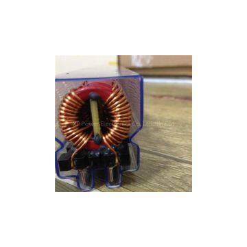 Common Mode Choke Coil With TubeUS$ 0.45 - 0.45MOQ: 2000 PiecesPlace of Origin: ChinaModel Number: XP-2612XP Power Electronics Co. Ltd
 Through-Hole Common Mode ChokesNegotiableMOQ: 1 PiecePlace of Origin: ChinaShaanxi Gold-Stone Electronics Co.,LTD