Product Description
I. Overview
Yokogawa UP55A-001-11-00 is a powerful programmable single-loop controller that holds an important position in the field of industrial automation control. With advanced technology and excellent performance, it provides precise and reliable control support for various industrial production processes. In its model, "UP55A" represents the product series, while "001-11-00" is the specific specification code, which determines the characteristics of the device in terms of functional configuration, communication interfaces, etc. This device is usually applicable to industrial scenarios that require precise control of physical quantities such as temperature, pressure, and flow, helping enterprises achieve efficient and stable production processes.

II. Technical Specifications
Measured value input: Supports universal input types, including thermocouple (TC), resistance temperature detector (RTD), millivolt (mV), volt (V), milliampere (mA), etc. This diversified input method enables it to adapt to various types of sensors, meeting the diverse measurement needs in complex industrial environments. The measurement accuracy can reach ±0.1% of the full scale, ensuring accurate measurement of physical quantities and laying a solid foundation for subsequent precise control.
Control cycle: The control cycle time can be set to 100 milliseconds or 200 milliseconds. A shorter control cycle time allows the device to quickly respond to changes in measured values, adjust the control output in a timely manner, effectively improving the timeliness and stability of control, which is particularly important for industrial processes that require rapid adjustment.
Display part: The measured value display part adopts a 14-segment 5-digit color LCD screen with a bar graph display. The color LCD screen can clearly present information such as measured values, set values, and the operating status of the device, and distinguish them through different colors and display modes, facilitating operators to intuitively obtain key data. The bar graph display shows the changing trend of measured values in an intuitive graphical way, helping operators understand the operation of the system more quickly.
Control output: There are various types of control outputs, including relays, voltage pulses, currents, etc. Relay output can be used to control the start and stop of high-power equipment, with high load capacity; voltage pulse output is suitable for controlling equipment with high response speed requirements; current output can realize precise control of analog equipment. There are various control algorithms, including ON/OFF control, PID (continuous, time proportion) control, heating/cooling control, position proportion control, etc. These control algorithms can flexibly select appropriate control strategies according to the needs of different industrial processes, ensuring that the physical quantity of the controlled object is stable near the set value.
Contact input and output
Contact input (DI): The standard configuration is 8, which can be expanded to 9 at most. Contact input has various functions, which can be used for operations such as mode number switching, PID number switching, A/M (automatic/manual) switching, etc. Through the input of external contact signals, the switching of equipment operation modes and the adjustment of control parameters can be conveniently realized, improving the flexibility and convenience of equipment operation.
Contact output (DO): The standard configuration is 8, which can be expanded to 18 at most. Contact output can be used for functions such as PV events (e.g., measured value reaching a specific threshold), time events (e.g., timing trigger), alarms (including various types of alarms such as upper limit of measured value, lower limit of measured value, upper limit of deviation, etc.). Through contact output signals, it can timely trigger the actions of external equipment, such as alarm indicators lighting up, alarm sounds, emergency stop of related equipment, etc., ensuring the safe operation of industrial production processes.
Program mode: It has a powerful program control function, which can carry up to 30 program modes with a total of 300 segments, and each program mode can contain up to 99 segments. By pre-writing program modes, the device can automatically perform control operations according to the set time-physical quantity change curve, realizing the automation of complex industrial production processes. For example, in the heat treatment process, according to the characteristics and processing requirements of metal materials, the corresponding program mode can be written to control the temperature change during heating and cooling, ensuring that the metal materials obtain the ideal organizational structure and performance.
Communication interfaces
Ethernet (Modbus/TCP): Supports Ethernet communication and follows the Modbus/TCP protocol. Through the Ethernet interface, the device can be easily connected to the factory automation network to realize data transmission and remote control with upper computers, other controllers, or intelligent devices. The high data transmission rate enables the device to upload measurement data, operating status and other information in real time, and receive control commands and parameter settings sent by the upper computer, facilitating the centralized monitoring and management of the production process.
RS-485 communication (Modbus/RTU, inter-device communication, cooperative operation, PC link, ladder diagram communication): Equipped with an RS-485 communication interface, supporting the Modbus/RTU protocol, which can realize point-to-point communication or multi-node communication between devices. In inter-device communication, multiple UP55A-001-11-00 devices can perform data interaction and cooperative work through the RS-485 interface to jointly complete complex control tasks. When linking with a PC, the device can be connected to a computer through the RS-485 interface, and special software can be used for device parameter setting, data recording and analysis, etc. In addition, it also supports ladder diagram communication, which is convenient for engineers to use ladder diagram programming to perform logical control on the device.
Open network (PROFIBUS-DP, CC-Link, DeviceNet): Supports multiple open network protocols, such as PROFIBUS-DP, CC-Link, DeviceNet, etc. This enables the device to seamlessly integrate with industrial automation equipment of different brands and types, building large-scale and complex industrial automation control systems. In industrial production lines, through the open network, UP55A-001-11-00 can perform high-speed and reliable data communication with PLCs, sensors, actuators and other equipment, realizing the automatic operation and cooperative control of the entire production line.
Power supply related
Instrument power supply: Supports wide voltage input, with a power supply voltage range of 100-240VAC (+10%, -15%), or 24VDC/AC (+10%, -15%) (optional specification). This wide voltage design enables it to adapt to the power supply conditions of different regions and industrial sites, reducing equipment failures caused by power supply problems, and improving the versatility and reliability of the device.
Energy consumption: The maximum energy consumption of the device during operation is 18VA. The relatively low energy consumption helps reduce the operating costs of enterprises and conforms to the development trend of energy conservation and environmental protection.
Dimensions and weight: Adopting a compact design, the depth of the device is only 65mm, and the overall size is small, which is convenient for installation in control cabinets or equipment with limited space. Its maximum weight is 0.5 kg, and the light weight also brings convenience to the installation and maintenance of the device.
III. Functional Highlights
Advanced control algorithm: It uses a complete PID control algorithm, and each control algorithm has 5 control calculation/output modes. The PID control algorithm can accurately adjust the control output through proportional, integral, and differential operations according to the deviation between the measured value and the set value, effectively suppressing the fluctuation of physical quantities and ensuring high precision and stability of control. For semiconductor manufacturing processes with extremely high temperature control requirements, by reasonably setting PID parameters, UP55A-001-11-00 can control the temperature within an accuracy range of ±0.1°C, meeting the strict requirements for temperature stability in the semiconductor production process.
Ladder diagram sequence control function: Standardly equipped with a ladder diagram sequence control program. The ladder diagram programming method is intuitive and easy to understand, and engineers can realize complex logical control functions by drawing ladder diagrams. In industrial automation production lines, using the ladder diagram sequence control function, the start, stop, operation sequence of equipment and various condition judgments can be programmed and controlled, realizing the automatic operation and intelligent management of the production line. For example, in a production line composed of multiple motors, valves and other equipment, through ladder diagram programming, the start-stop sequence and operation time of each equipment can be precisely controlled according to the production process requirements, ensuring the efficient and stable operation of the production line.
Convenient operation interface: Equipped with an intuitive menu-guided operation interface and a full-text display screen. Operators can easily complete operations such as parameter setting and operation mode selection of the device through simple key operations without complex training. The full-text display screen can clearly show the operating status of the device, current measured value, set value, and various alarm information, etc., facilitating operators to monitor the operation of the device in real time. At the same time, the device adopts easy-to-operate navigation keys and is equipped with user-definable function keys. Users can set common functions on the function keys according to their own operating habits, further improving the convenience and efficiency of operation.
Multi-language display function: Supports multi-language display, including common languages such as English, Spanish, French, German, etc. This function enables the device to be widely used worldwide, eliminating language barriers for operators in different countries and regions, and facilitating the promotion and use of the device. Whether in industrial sites in Europe, America or Asia, operators can switch the device display language to a language they are familiar with through settings, and smoothly operate and monitor the device.
Fault diagnosis and protection functions: It has perfect fault diagnosis and protection mechanisms. It can monitor the working status of the sensor in real time, timely detect and report sensor faults, such as sensor open circuit, short circuit, signal abnormality, etc., effectively reducing inaccurate control or production accidents caused by sensor faults. At the same time, the device is also equipped with various protection functions such as over-temperature, over-current, and under-voltage. When abnormal conditions are detected, it can immediately take corresponding protection measures, such as cutting off the output power, to prevent damage to the device and the production process, and ensure production safety and device reliability. During the operation of the device, if an open circuit of the temperature sensor is detected, the device will immediately send an alarm signal and stop related control operations to avoid losses caused by temperature out of control.
Programmable process control: Supports programmable ramp and soak functions. By pre-writing programs for changes in temperature or other physical quantities, the device can automatically perform operations such as heating, heat preservation, and cooling according to the set time-physical quantity curve, realizing complex batch processing and process flow control. In the plastic molding process, according to the characteristics and molding requirements of plastic materials, the corresponding program can be written to control the temperature change of the mold, so that the plastic can flow and form at a suitable temperature, improving the quality and production efficiency of plastic products.
IV. Common Faults and Solutions
Inaccurate measured values
Possible causes: Sensor faults, such as aging, damage, loose wiring, etc., leading to abnormal measurement signals; input signal interference, the presence of strong electromagnetic fields and other interference sources around, affecting the transmission of sensor signals; faults in the input module of the device, which cannot correctly process the signals input by the sensor.
Solutions: Check the working status of the sensor, use standard instruments to calibrate and test the sensor. If the sensor is damaged or aged, replace it with a new one in time and ensure that the sensor wiring is firm. Check for surrounding interference sources and take anti-interference measures such as shielding and grounding, such as shielding the sensor cable and ensuring good grounding of the device. If the input module is suspected to be faulty, contact professional maintenance personnel to inspect and repair the input module, and replace it if necessary.
Abnormal control output
Possible causes: Unreasonable setting of control algorithm parameters, which cannot adapt to the characteristics of the actual controlled object; faults in the output module, such as relay contact adhesion, damage to the voltage pulse output circuit, failure of the current output chip, etc.; faults in the actuator, such as broken heating wires, failure of the refrigeration compressor, valve jamming, etc., causing the control output to fail to act on the actuator normally.
Solutions: According to the characteristics and operation of the actual controlled object, readjust the control algorithm parameters. The optimal parameter combination can be found through the auto-tuning function if the device has it or manual debugging. Check the output module. For relay output, observe whether the relay contacts act normally. If the contacts are Adhesion,replace the relay; for voltage pulse and current output modules, use professional testing equipment to detect circuits and chips, and repair or replace them if there is a fault. Check the actuators, inspect and repair actuators such as heating wires, refrigeration compressors, valves, etc., to ensure their normal operation.
Communication faults
Possible causes: Damaged communication cables, loose interfaces, leading to interruption of communication signals; incorrect setting of communication parameters, such as baud rate, data bits, stop bits, parity bits, etc., which do not match the upper computer or other devices; faults in the communication module of the device, which cannot send and receive data normally.
Solutions: Check whether the communication cable is damaged or broken, and whether the interface is tightly plugged. If there is a problem, replace the cable or re-plug the interface in time. Carefully check the communication parameters to ensure that they are consistent with those of the upper computer or other devices communicating with it. If the communication parameters are set correctly but communication still cannot be achieved, there may be a fault in the communication module of the device. Contact professional maintenance personnel to inspect and repair the communication module, such as replacing the damaged communication chip and repairing the communication circuit.
Abnormal program operation
Possible causes: Program writing errors, such as logical errors, parameter setting errors, etc., causing the program to fail to run as expected; faults in the device's memory, resulting in loss or damage of program data; interference during operation, leading to abnormal program execution.
Solutions: Carefully check the program code, find out logical errors and parameter setting errors, and correct and optimize the program. If the memory is suspected to be faulty, try to back up the program to an external storage device, then format the device's memory and rewrite the program. If the program operation is interfered, take anti-interference measures, such as adding a shield cover, optimizing the grounding of the device, etc., to ensure the stable operation of the program.

 1YrAnshun, Guizhou, China
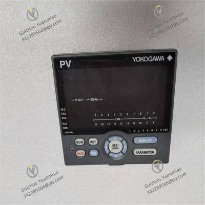


 yezi
Hi there! Welcome to my shop. Let me know if you have any questions.
yezi
Hi there! Welcome to my shop. Let me know if you have any questions.