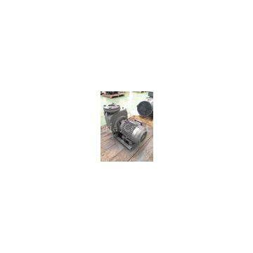
Home > Products > Self Priming Sewage Pump > High Head Self Priming Sewage Pump , Drainage Industrial Sewage Pump
High Head Self Priming Sewage Pump , Drainage Industrial Sewage Pump
- 0 Set / Sets per Month
- T/T L/C D/P D/A
- 7 days
You May Like
-
15 kW Portable Self Priming Sewage Pump GB2 / IE3 High Efficiency Motor
-
Wastewater Treatment Stainless Steel Self Priming Pump 2900 Rpm With Semi Open Impeller
-
Single Stage Stainless Steel Self Priming Sewage Pump Low Noise With Coupling
-
Solid Free Portable Self Priming Sewage Pump Installation Coupling Stage
-
220V Electrical Self Priming Centrifugal Pump Coupling Connected Stable Operation
-
Submersible Most Efficient Low Speed Propeller Mixer IP68 Protection Grade
Product Details
| Brand Name | GSD | Place of Origin | China | |
| Model Number | GMP |
Product Description
Certification:ISO CE
High Head Self Priming Sewage Pump , Drainage Industrial Sewage Pump
Application
a) Industrial water supply and drainage.
b) Building site water supply and drainage.
c) For wastewater treatment plant
Main features
a) Adopts acid resisting stainless steel (AISI316) in valve body, which has unique
b) Solid-passing allowance.
c)?Painting & pump material are available for OEM requirement.
d) Low noise
e) Acid alkali resistance, and comply with sanitary requirements for foods.
f) Stable operation
Structure & Material
| No. | Name | Material (GB) | Material (JIS) |
| 1 | Base | Q235A | SS400 |
| 2 | Pump body | HT200 | FC200 |
| 3 | Plug | Q235A | SS400 |
| 4 | Gaskets | NBR | NBR |
| 5 | Cover | HT200 | FC200 |
| 6 | Impeller | HT200 | FC200 |
| 7 | Check | NBR | NBR |
| 8 | Check base | HT200 | FC200 |
| 9 | O-Ring | NBR | NBR |
| 10 | Seal ring | ZCuSn10Pb5 | Tin-Bronze |
| 11 | Bracket | HT200 | FC200 |
| 12 | Motor | - | - |
| 13 | Mechanical Seal | Sic-Sic | Sic-Sic |
| 14 | Key | 3Cr13 | SUS420J2 |
| 15 | Lock washer | 0Cr18Ni9 | SUS304 |
| 16 | Impeller Nut | 0Cr18Ni9 | SUS304 |
| 17 | Separator | HT200 | FC200 |
Before assembly of the pump, the parts shall be checked first to see if there is any defect that will affects the assembly, clear the burr and wash clean, then the assembly can be carried out.
|
1. |
The connection bolts and plugs at every place shall be tightened on correspondent parts respectively in advance. |
| 2. | O-ring shall be placed on the back lid or middle support bracket in advance. |
|
3. |
The seal ring shall be installed into the back lid or middle support bracket in advance and it shall be locked tightly with screws. |
|
4. |
The separating board shall be installed into the pump body in advance, and it shall be locked tightly with bolts. |
|
5. |
Install the back lid on the bearing body parts or install the middle support bracket on the electrical machinery and lock it tightly with bolts. |
| 6. | Install the above parts into the pump body and lock the nut tightly. Twist the main shaft, it shall have a flexible rotation and no friction is allowed. |
| 7. |
Install the valve flap and valve base on the pump body and lock the nut tightly. Pay attention to the direction of the valve flap and valve base. |
| 8. | Carry out the static pressure test with a pressure 2.5 times more than the work pressure, keep the pressure for 5 minutes to see if there is any leakage or perspiration. |
| 9. |
Place the electrical machinery and pump on the chassis, adjust the concentration which requires to be under 0.05mm and lock all the bolts tightly. |
Performance parameter


