Product Description
I. Overview
Metso D200175 is a high-precision drive control module, whose core positioning is to provide a full-link solution of "drive signal generation - speed closed-loop control - load monitoring - fault protection" for heavy-duty drive systems such as mine belt conveyors, auxiliary drives of metallurgical rolling mills, and conveying equipment in building materials production lines. As a key component of Metso's drive control systems (e.g., Metso Outotec Drive System, Metso DNA Integrated Control Platform), its essence lies in achieving precise speed regulation of asynchronous and synchronous motors through high-performance motor control algorithms and highly reliable hardware circuits. At the same time, it real-time monitors key parameters of the drive system such as current, voltage, and temperature, and quickly responds to abnormal working conditions like overload, stalling, and overheating. It is particularly suitable for harsh industrial environments with high load, high vibration, and strong electromagnetic interference (e.g., underground mine belt conveyors, drive units of crushers in cement production lines).
Adopting a fanless and compact hardware architecture, it is compatible with various speed feedback signals from incremental encoders and absolute encoders, and supports multiple drive output methods such as PWM (Pulse Width Modulation) and analog signals, enabling direct driving of frequency converters or servo drives. Its integrated dedicated functions including overload protection, stall detection, and motor temperature monitoring can effectively prevent mechanical failures and electrical damage to the drive system; when used with Metso's drive management software, it can realize drive parameter tracing and health status evaluation, forming a complete closed loop of "control - monitoring - diagnosis". Whether it is the constant speed control of belt conveyors, load-adaptive regulation of crushers, or precise speed synchronization of auxiliary equipment for rolling mills, the D200175 can improve the stability and reliability of the drive system through specialized design, making it a core equipment for process industries to achieve drive automation upgrades.

II. Technical Parameters
(I) Signal Input/Output Parameters
Input Channel Configuration
Speed Feedback Input: 2 independent encoder input channels, compatible with incremental encoders (A/B phase, 5V/24V, maximum frequency 500kHz) and absolute encoders (RS485 interface, supporting Modbus protocol). It can real-time collect motor speed (0-3000rpm) and direction signals, with a speed measurement accuracy of ±0.01%, ensuring a speed control error of ≤0.1%.
Status Signal Input: 12 isolated digital input (DI) channels, supporting 24V DC signals, with an input response time of ≤1ms. It is suitable for signals from motor overload protection switches, emergency stop buttons, drive system limit switches, and load sensors. The anti-interference voltage is ≥250V AC (for 1 minute), preventing false triggers caused by electromagnetic interference in industrial sites.
Control Command Input: 1 analog control command input (4-20mA DC, corresponding to a speed of 0-3000rpm) or 1 digital control command input (24V DC, for start/stop and forward/reverse control), supporting input of manual/automatic control mode switching signals.
Output Channel Configuration
Drive Control Output: 2 PWM output channels (pulse frequency 0-20kHz, duty cycle 0-100%) or 1 analog output channel (4-20mA DC), which can directly drive frequency converters or servo drives. The output accuracy is ±0.2% FS, with a load capacity of ≤2A (for PWM output) and ≤500Ω (for analog output), ensuring a motor speed regulation accuracy of ≤0.1%.
Alarm and Status Output: 6 relay output (DO) channels, each with a rated load current of 5A@250V AC / 10A@30V DC, supporting configurable normally open/normally closed contacts. They are used for drive system fault alarms (e.g., overload, stalling, overheating) and status indication (e.g., running/stopped, forward/reverse rotation), with a mechanical life of ≥10 million cycles and an electrical life of ≥100,000 cycles (under rated load).
(II) Electrical and Performance Parameters
Power Supply and Power Consumption
Supply Voltage: 24V DC (with ±15% fluctuation tolerance), compatible with commonly used industrial DC power modules (e.g., 24V/10A switching power supplies), eliminating the need for dedicated power supply equipment.
Standby Power Consumption: ≤4W; Power consumption under full load: ≤15W. The low-power design is suitable for emergency drive control scenarios with battery backup (e.g., emergency belt conveyors in underground mines).
Control Performance
Speed Control Accuracy: The motor speed control accuracy is ≤0.1%, with a speed regulation range of 0-3000rpm, supporting fine speed adjustment (minimum adjustment step 1rpm). It is suitable for scenarios such as constant speed control of belt conveyors and load-adaptive regulation of crushers.
Response Speed: The control command response time is ≤50ms, and the speed deviation correction time is ≤300ms, which can quickly suppress speed deviations caused by load fluctuations (e.g., speed drop ≤0.5% when the belt conveyor is loaded).
Dedicated Control Algorithms: Built-in PID speed regulation algorithm, load-adaptive algorithm, and stall detection algorithm. It can dynamically adjust the drive output according to load changes (e.g., automatically increase drive power when the load of the belt conveyor increases), identify motor stalling (e.g., speed feedback ≤10rpm and drive current exceeding 200% of the rated value), and trigger protective actions.
(III) Environmental and Compatibility Parameters
Environmental Adaptability
Operating Temperature: -25℃~+70℃, humidity 5%~95% RH (no condensation). It can operate stably in environments such as underground mines (high temperature and humidity), metallurgical workshops (high dust and temperature), and building materials production lines (high dust) without additional temperature control devices.
Protection Level: IP20 (module itself); when used with Metso's dedicated sealed enclosure, it can be upgraded to IP54, effectively isolating dust and moisture and adapting to dusty and humid industrial scenarios.
Anti-interference and Anti-vibration: Complies with IEC 61000-4-2 (ESD ±15kV air discharge) and IEC 61000-4-3 (radiated immunity 10V/m) standards. It can withstand mechanical vibration of 10-500Hz (acceleration 2g), ensuring stable signals in the vibration environment of heavy-duty drive equipment.
System Compatibility
Drive Equipment Adaptability: Natively compatible with Metso Outotec series frequency converters and servo drives, and also supports third-party drive equipment (e.g., Siemens MM440 frequency converter, ABB ACS510 frequency converter). It can adapt to the control requirements of frequency converters of different brands through parameter configuration.
Communication Interface: Standard RS485 communication interface (Modbus RTU protocol), with an optional Ethernet module (Profinet protocol). It can be connected to DCS/PLC systems, supporting the issuance of drive control commands, reading of speed feedback, and uploading of fault information to achieve remote monitoring and centralized management.
III. Functional Features
(I) High-Precision Speed Closed-Loop Control for Heavy-Duty Drive Scenarios
Built-in dedicated speed control algorithms to solve the problems of insufficient precision and poor load adaptability of traditional drive control:
PID Speed Regulation Algorithm: Aiming at the characteristics of large inertia and frequent load fluctuations of heavy-duty motors, it optimizes the PID parameter self-tuning logic. It can dynamically adjust the proportional (P), integral (I), and derivative (D) parameters according to speed deviations to avoid speed overshoot (e.g., speed overshoot<1%). It is suitable for scenarios such as constant speed control of belt conveyors (speed error ≤0.1%) and load-adaptive regulation of crushers.
Load-Adaptive Control: Real-time monitors the motor load current (collected through DI or AI channels). When the load increases (e.g., material accumulation on the belt conveyor), it automatically increases the drive output power to maintain stable speed (speed drop ≤0.5%); when the load exceeds 120% of the rated value, it triggers an overload warning to prevent motor damage due to overload.
Stall Detection and Protection: Real-time compares the drive command with the speed feedback. When the speed feedback ≤10rpm and the drive current exceeds 200% of the rated value (for 2 consecutive seconds), it determines that the motor is stalled, immediately stops the drive output, triggers a DO alarm (e.g., "E02: Motor Stall"), and cuts off the motor power supply to prevent motor burnout or drive mechanism damage.
For example, in the control of mine belt conveyors, the module controls the speed error of the belt conveyor within ±1rpm (rated speed 1000rpm) through the PID speed algorithm. Even if the load of the belt conveyor suddenly increases from 50% to 100%, the speed fluctuation is still ≤5rpm, effectively avoiding material accumulation or belt slipping.
(II) Multi-Dimensional Status Monitoring for Full-Status Management of Drive Systems
Supports comprehensive monitoring of the drive system's speed, load, electrical parameters, and mechanical status, forming a complete status profile:
Speed and Direction Monitoring: Collects real-time motor speed (0-3000rpm) and direction signals through 2 encoder input channels, displays the speed value and direction status (forward/reverse rotation) on the upper computer, and records the speed change trend (e.g., storing data once per second).
Load and Electrical Parameter Monitoring: Collects the motor overload protection signal through the DI channel, and collects the motor operating current (4-20mA feedback) through the extended AI channel. When the current exceeds the rated value (e.g., 2A), it triggers an overload warning.
Mechanical Status Monitoring: Collects signals from the drive system's limit switches (e.g., belt conveyor deviation switch, crusher spindle limit) and emergency stop buttons through the DI channel. When the limit switch is triggered, it immediately stops the drive output to prevent collision damage to the mechanical structure.
In the control of auxiliary drives for metallurgical rolling mills, the module can precisely control the speed of the rolling mill's auxiliary roller table (error ≤0.1%) by monitoring the motor speed and load current, while preventing motor overload caused by roller table jamming, reducing the failure rate of the drive system by 30%~40%.
(III) Flexible Interlocking Logic for Safe Operation of Drive Systems
Supports custom drive control interlocking logic to meet the safety requirements of process industries:
Emergency Stop Interlocking: Can be configured with interlocking logic such as "Emergency stop button triggered (DI1) → Stop drive output (PWM/AO) + Cut off motor power supply (DO1)" and "Belt deviation (DI2) → Decelerate to stop (DO2)", with a response time of ≤50ms. It is suitable for scenarios such as mine belt conveyors and metallurgical roller tables.
Bumpless Manual/Auto Switching: Supports bumpless switching between local manual adjustment (e.g., setting speed via a knob) and remote automatic control (e.g., DCS command). The speed fluctuation during switching is ≤0.5%, avoiding working condition disturbances (e.g., interruption of material conveying by the belt conveyor).
Fault Degraded Operation: When the module communication is interrupted, it automatically maintains the current speed output or executes a preset fault action (e.g., reducing to a safe speed of 500rpm) to prevent equipment damage or production interruption caused by drive system out of control.
In the drive control of crushers in building materials production lines, when the crusher spindle limit switch is triggered (DI3), the module immediately triggers the interlocking logic, stops the drive output within 100ms, and cuts off the crusher power supply to prevent mechanical damage caused by spindle overtravel.
(IV) Convenient Operation & Maintenance and Data Tracing for Reduced Management Costs
Status Visualization: The module panel is equipped with speed indicator lights (segmented display of 0-3000rpm), fault alarm lights (red), and operation status lights (green, distinguishing forward/reverse rotation), which can intuitively determine the current status of the drive system (e.g., the indicator light showing "800rpm" means the current speed is 800rpm, and a flashing red light indicates a stalling fault).
Data Storage and Tracing: Built-in 1-year historical data storage function, recording motor speed, load current, fault information, control commands, etc. It supports data export via RS485 for drive system health evaluation (e.g., statistics of motor operating time, analysis of overload frequency).
Online Parameter Configuration: Remotely configures PID parameters, interlocking logic, and alarm thresholds (e.g., overload current threshold, stall determination time) through Metso's dedicated software (e.g., Metso Drive Manager) without on-site module disassembly. The modification time for a single parameter is ≤1 minute, reducing operation and maintenance time and costs.
IV. Application Scenarios
(I) Mining Industry: Belt Conveyor Drive Control
In the drive system of underground belt conveyors in metal mines, the D200175 plays a core control role:
Signal Collection: Encoder Input 1 (PI1) collects the encoder signal (A/B phase, 500kHz) of the belt conveyor drive motor, providing real-time speed feedback (0-1000rpm); DI1-DI4 channels are connected to the belt deviation switch, pull-cord emergency stop button, motor overload protection switch, and level sensor signals; the extended AI1 channel collects the motor operating current (4-20mA corresponding to 0-5A).
Control Logic: Under normal working conditions, it receives the 4-20mA control command from the DCS (AI2, corresponding to a speed of 0-1000rpm), drives the frequency converter through PWM output, and controls the belt conveyor speed (e.g., 800rpm); when the level sensor detects material accumulation (DI4 triggered), it automatically reduces the speed to 500rpm to prevent material overflow.
Fault Protection: When the belt deviates (DI1 triggered) or the pull-cord emergency stop is activated (DI2 triggered), it immediately stops the PWM output (to shut down the drive frequency converter), and at the same time triggers DO1 to cut off the motor power supply and DO2 to activate the braking device; when the motor current exceeds 5A (AI1 out of range), it determines an overload, triggers DO3 for alarm, and uploads fault information to the mine dispatch center.
(II) Metallurgical Industry: Drive Control of Rolling Mill Auxiliary Roller Tables
In the drive system of auxiliary roller tables for hot-rolled steel plate production line rolling mills, the application value of the module is significant:
High-Precision Speed Control: Encoder Input 1 (PI1) collects the encoder signal (absolute encoder, RS485) of the roller table motor, providing speed feedback (0-500rpm); it receives the digital control command (DI5, forward/reverse rotation) and analog speed command (AI1, 4-20mA corresponding to 0-500rpm) from the rolling mill main control system, drives the servo drive through analog output (AO1), and controls the roller table speed (error ≤0.5rpm).
Load-Adaptive Regulation: Collects the roller table motor load current (4-20mA corresponding to 0-3A) through the AI2 channel. When the steel plate enters the roller table (load increases, current rises from 1A to 2.5A), it automatically increases the drive output to maintain stable speed (fluctuation ≤1rpm).
Interlocking Protection: When the roller table limit switch is triggered (DI6, steel plate overtravel), it immediately stops the drive output, and at the same time triggers DO1 to cut off the roller table power supply to prevent collision damage to the steel plate; when communication is interrupted, it automatically maintains the current speed (e.g., 300rpm) to ensure production continuity.
(III) Building Materials Industry: Drive Control of Crushers in Cement Production Lines
In the drive system of crushers (e.g., jaw crushers) in cement production lines, the module realizes the following functions:
Speed and Load Control: Encoder Input 1 (PI1) collects the encoder signal (incremental, 500kHz) of the crusher spindle motor, providing speed feedback (0-1500rpm); it drives the frequency converter through PWM output to control the spindle speed (e.g., 1000rpm); it collects the crusher over-torque sensor signal through the DI3 channel. When the torque exceeds 120% of the rated value, it automatically reduces the speed to 800rpm to prevent spindle overload.
Stall Protection: Real-time compares the drive command with the speed feedback. When the speed feedback ≤10rpm (for 2 consecutive seconds) and the drive current exceeds 200% of the rated value, it determines material stalling, immediately stops the drive output, triggers DO2 for alarm ("E02: Motor Stall"), and uploads fault information to the cement plant DCS.
Remote Monitoring: Uploads the crusher speed, load current, and fault information to the workshop MES system via the Profinet protocol. Dispatch personnel can remotely check the drive system status and modify speed parameters (e.g., adjusting from 1000rpm to 1100rpm) to achieve remote operation and maintenance.

 1YrAnshun, Guizhou, China
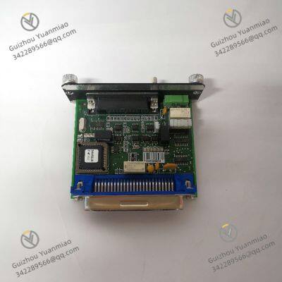


 yezi
Hi there! Welcome to my shop. Let me know if you have any questions.
yezi
Hi there! Welcome to my shop. Let me know if you have any questions.