Product Description
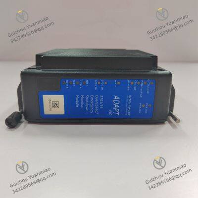
BENTLY NEVADA (now part of Baker Hughes) 3701/55 ADAPT is an industrial-grade online condition monitoring module specifically designed for rotating machinery (such as steam turbines, generators, compressors, pumps, etc.). As a member of the ADAPT (Advanced Diagnostic and Predictive Technology) series, it is core-positioned for "distributed, high-precision, multi-parameter monitoring". By real-time collecting key operational data of machinery (e.g., vibration, shaft displacement, rotational speed), it enables equipment health status diagnosis, early fault warning, and trend analysis. Widely used in petrochemical, power generation, nuclear power, metallurgy, and other fields with extremely high requirements for equipment reliability, it serves as a critical monitoring unit to ensure the long-cycle safe operation of rotating machinery. The following provides a detailed explanation from dimensions including technical parameters, hardware structure, functional characteristics, application scenarios, and installation & maintenance, ensuring the accuracy and completeness of information.
I. Basic Technical Parameters and Identification Information

II. Hardware Structure and Core Components1. Core Signal Processing Unit
Main Controller: Adopts a 32-bit industrial-grade microprocessor (MCU, typically NXP i.MX series) with an operating frequency ≥ 800MHz. It supports real-time signal processing algorithms (e.g., FFT spectrum analysis, order analysis, trend calculation) and has a data processing delay ≤ 10ms (ensuring the real-time performance of monitoring data to meet the requirement of rapid fault response).
Signal Conditioning Module:
Preamplifier circuit: Performs low-noise amplification (adjustable gain, 1~1000x) on weak sensor signals (e.g., mV-level signals output by eddy current sensors) to suppress background noise (signal-to-noise ratio ≥ 80dB);
Filter circuit: Built-in programmable low-pass/high-pass filters (adjustable cutoff frequency 0.1Hz~10kHz) to filter out on-site interference signals (e.g., power grid harmonics, mechanical high-frequency noise);
Temperature compensation circuit: Aiming at the characteristic of eddy current sensors being affected by ambient temperature, a built-in PT100 temperature acquisition channel is provided to real-time compensate for temperature drift (compensation range -40~70℃, ensuring displacement measurement accuracy).
Data Acquisition Module:
Analog-to-Digital Converter (ADC): 16-bit resolution, maximum sampling rate 100kHz (single channel), supporting synchronous sampling (multi-channel sampling time difference ≤ 1μs) to ensure time consistency of multi-parameter (e.g., vibration, displacement, rotational speed) acquisition;
Buffer unit: Built-in 512KB SRAM buffer for temporarily storing real-time acquired data to avoid data loss (supports data retention for 10s after power failure to prevent critical data loss caused by sudden power outage).
2. Interface and Communication Unit
Sensor Interfaces (located on the front of the module, arranged by channel):
Signal input terminals: 4 groups of differential input terminals (each group corresponding to 1 channel of sensor signal, e.g., vibration + Keyphasor, displacement + temperature), supporting BNC connectors or screw crimp terminals (compatible with different sensor cables);
Sensor power supply terminals: 2 groups of isolated DC 15V/24V power output (providing independent power supply for eddy current sensors and acceleration sensors to avoid interference with the module’s main power supply);
Keyphasor signal interface: 1 group of dedicated Keyphasor input terminals (supporting 0~10V pulse signals or sine signals for rotational speed calculation and phase synchronization).
Communication Interfaces (located on the back of the module):
Industrial Ethernet interfaces: 2 RJ45 ports (supporting Ethernet/IP and Modbus TCP protocols) for communication with upper computers (e.g., condition monitoring software System 1) or PLCs, with adaptive data transmission rate of 10/100Mbps;
Serial communication interface: 1 RS-485 port (supporting Modbus RTU protocol) for networking with local display terminals or other monitoring modules (supporting "daisy-chain" topology for multi-modules, with a maximum of 32 modules in series);
Alarm output interfaces: 4 dry contact output terminals (normally closed/normally open optional, corresponding to four states: "Warning", "Danger", "Fault", "Normal") for driving on-site alarm lights or relays.
3. Auxiliary Function Unit
Status Indication Unit: The front panel is equipped with 6 LED indicators (Power, Communication, Acquisition, Warning, Danger, Fault), with status distinguished by color (green = normal, yellow = warning, red = danger/fault), facilitating on-site personnel to quickly judge the module’s operating status;
Storage Unit: Built-in 4GB Flash memory for storing historical monitoring data (e.g., vibration spectra, trend curves) and user configuration parameters (e.g., alarm thresholds, sensor calibration data). It supports automatic storage at adjustable time intervals (1s~1h), with a data retention time ≥ 1 year (calculated based on storage at 1-minute intervals);
Calibration Unit: Supports built-in automatic calibration function (using the module’s own standard signal source to regularly calibrate ADC accuracy, with adjustable calibration cycle of 1~12 months). Calibration can be completed without disassembling the module, reducing maintenance costs.

III. Core Functions and Technical Characteristics1. Multi-Parameter Real-Time Monitoring and Data Acquisition
Comprehensive Condition Monitoring: It can simultaneously collect core operational parameters of rotating machinery, covering four dimensions: "vibration-position-rotational speed-temperature":
Vibration monitoring: Supports radial vibration (bearing housing vibration, shaft vibration) and axial vibration (coupling vibration), and can measure characteristic values such as peak value, peak-to-peak value, RMS (Root Mean Square), crest factor, and kurtosis (for judging faults such as bearing wear and rotor unbalance);
Position monitoring: Shaft displacement (e.g., axial displacement of steam turbine rotor, judging whether static and dynamic components are rubbing) and shaft eccentricity (rotor eccentricity, monitoring rotor bending status);
Rotational speed monitoring: Real-time calculation of rotational speed (RPM), rotational speed fluctuation (judging whether the rotor is unstable), and order (vibration frequency component synchronized with rotational speed, for diagnosing faults such as rotor unbalance and misalignment);
Temperature monitoring: Bearing temperature and stator temperature (judging whether the lubrication system is normal and preventing bearing burnout due to overheating).
Flexible Data Acquisition Modes:
Continuous acquisition mode: 24/7 uninterrupted data acquisition (adjustable sampling rate 10~100kHz) for real-time monitoring and fault alarm;
Intermittent acquisition mode: Data acquisition at set intervals (1min~1h adjustable) for long-term trend analysis (e.g., tracking equipment aging trends);
Event-triggered acquisition mode: When the monitored value exceeds the preset threshold (e.g., excessive vibration, abnormal rotational speed), high-speed acquisition is automatically activated (sampling rate increased to 100kHz), and data before and after the fault occurrence is recorded (adjustable pre-trigger time 1~10s), providing complete data support for fault diagnosis.
2. Fault Diagnosis and Early Warning Functions
Built-in Diagnostic Algorithms: Based on BENTLY’s decades of experience in rotating machinery monitoring, it integrates a variety of mature diagnostic algorithms to identify common fault types:
Rotor unbalance: Judging whether the rotor has unbalance (e.g., blade wear, rotor fouling) by analyzing the amplitude change of the 1st-order vibration component (consistent with rotational speed frequency);
Misalignment: Analyzing the 2nd-order vibration component (twice the rotational speed frequency) to diagnose coupling or shafting misalignment (parallel misalignment, angular misalignment);
Bearing faults: Identifying wear of rolling bearing outer rings, inner rings, and rolling elements through high-frequency vibration analysis (above 10kHz) or changes in crest factor and kurtosis;
Rubbing faults: Monitoring sudden changes in axial displacement and vibration burr signals to warn of rotor-stator rubbing (e.g., steam turbine gland rubbing);
Oil whirl/oscillation: Analyzing the vibration component of 0.4~0.5 times the rotational speed frequency to diagnose oil film instability of plain bearings.
Multi-Level Alarm Mechanism:
Alarm levels: Supports three-level alarm settings — "Warning" (mild overrun, requiring attention), "Danger" (severe overrun, requiring shutdown inspection), and "Emergency" (sudden fault, requiring immediate shutdown);
Alarm triggering methods: Can be based on "absolute value triggering" (e.g., vibration peak-to-peak value > 50μm triggers warning) or "trend triggering" (e.g., vibration amplitude increase > 20% within 1 hour triggers warning);
Alarm output: When an alarm is triggered, it synchronously activates LED indicators (corresponding color lights up), dry contact output (driving external alarm equipment), and communication messages (sending alarm information to the upper computer), ensuring on-site and remote personnel are informed of the fault simultaneously.
3. Data Storage and Remote Management
4. Compatibility and Redundancy Design
Sensor Compatibility: Compatible with BENTLY’s full range of monitoring sensors (3300 XL eddy current sensors, 9200 acceleration sensors, etc.) and also supports third-party standard sensors (e.g., acceleration sensors complying with IEPE standards), reducing the cost for users to replace sensors;
System Compatibility: Supports seamless integration with other BENTLY monitoring products (e.g., 3500 protection system, 1701 communication gateway) to build an integrated "monitoring-protection-diagnosis" system; it can also be connected to third-party PLCs (e.g., Siemens S7, Rockwell ControlLogix) or DCS (e.g., Emerson DeltaV) to integrate into the user’s existing control system;
Redundancy Design:
Power supply redundancy: Supports dual-channel DC 24V input (main/backup power supply, automatically switching to the other channel when one channel is powered off, with switching time <100ms);
Communication redundancy: The Ethernet interface supports redundant configuration (dual network cards, automatically switching to the other channel when one communication channel fails) to ensure uninterrupted data transmission;
Module redundancy: Supports "1+1" redundancy configuration of multiple modules (the standby module automatically takes over the monitoring task when the main module fails), suitable for critical equipment (e.g., nuclear power main pumps, large compressors).

IV. Application Scenarios and Typical Deployments
Due to its characteristics of "high precision, high reliability, and strong diagnostic capabilities", the 3701/55 ADAPT is mainly applied in online condition monitoring scenarios of large-scale rotating machinery, as detailed below:
1. Power Industry (Core Scenario)
Applicable Equipment: Steam turbines, generators, feedwater pumps, forced draft fans, and induced draft fans of thermal power units; main pumps and steam generator circulating pumps of nuclear power units;
Deployment Method: 1~2 3701/55 ADAPT modules are configured for each key rotating equipment (e.g., one module for monitoring steam turbine rotor vibration and shaft displacement, and one module for monitoring generator stator vibration and bearing temperature). Modules are centrally installed in control cabinets in the control room, and sensors are installed on the equipment body (e.g., bearing housings, rotor shaft ends);
Core Roles:
Real-time monitoring of steam turbine rotor axial displacement (preventing unit damage caused by rubbing between static and dynamic components);
Early warning of generator bearing temperature rise (avoiding shutdown accidents caused by bearing burnout);
Predicting feedwater pump impeller wear through trend analysis (arranging maintenance in advance to avoid unplanned shutdowns).
2. Petrochemical Industry
Applicable Equipment: Main fans of catalytic cracking units, compressors (e.g., centrifugal compressors, reciprocating compressors), and oil transfer pumps;
Deployment Method: Modules are installed in explosion-proof control cabinets in the unit area (meeting Zone 2 explosion-proof requirements, with explosion-proof sensors), and sensors are directly installed on compressor bearing housings and pump shaft ends;
Core Roles:
Diagnosing compressor shafting misalignment (avoiding premature bearing wear caused by misalignment and extending service life);
Monitoring oil transfer pump vibration (warning of impeller cavitation or blockage to ensure stable crude oil transportation);
Recording vibration data during unit startup and shutdown (analyzing impact loads during startup and shutdown to optimize startup/shutdown curves).
3. Metallurgy and Mining Industry
Applicable Equipment: Main drive motors of rolling mills, blast furnace blowers, and mine crushers;
Deployment Method: Modules are installed in control cabinets in workshops (adapting to dusty environments and requiring regular cleaning), and sensors are installed on motor bearings and crusher rotors;
Core Roles:
Monitoring vibration of main drive motors of rolling mills (warning of gearbox wear to avoid steel plate scrapping caused by equipment faults during rolling);
Analyzing rotational speed fluctuations of blast furnace blowers (ensuring stable air pressure to avoid blast furnace wind cutoff affecting smelting).
V. Product Status and Installation & Maintenance1. Product Production and Supply Status
 II. Hardware Structure and Core Components1. Core Signal Processing Unit2. Interface and Communication Unit3. Auxiliary Function Unit

ABB 086370-001 Circuit Board
ABB 086339-501 Digital Input Module
ABB 086348-001 PC Board
ABB 086444-005 Measurement Process Board
ABB RMU610 2VAA008425R1 Repeater Mounting Unit
ABB CHBX01L 2VAA008574R1 Compact Bus Extender
ABB CHBX01R 2VAA008575R1 Compact Bus Extender
ABB UFC921A 3BHE024856P106 Communication Module
ABB PP886 3BSE092980R1 Operation Panel
ABB SUE3000 1VCF750090R0804 Maintenance Exchange Unit
ABB SUE3000 1VCR007346 G0032 REF542plus HMI Unit
ABB GFD563A101 Interface Module
 yezi
Hi there! Welcome to my shop. Let me know if you have any questions.


