Product Description
I. Product Overview
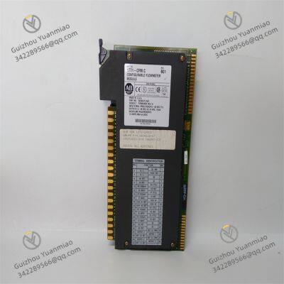
The Allen-Bradley 1771-CFM module is a communication function module in the PLC-5 series, with the full name of ControlNet Flexible Module. It is mainly used to realize flexible communication connections between the ControlNet network and other devices or systems. In the field of industrial automation, as control systems become increasingly complex and equipment becomes more diverse, data interaction between different networks and devices has become crucial. The 1771-CFM module, with its flexible communication capabilities, has become a key bridge connecting the ControlNet network with other systems, greatly improving the integration and data transmission efficiency of industrial automation systems.
The module adopts a compact design structure, with dimensions suitable for 1771 series I/O enclosures, allowing for easy installation in industrial control cabinets and saving installation space. The shell is made of high-strength industrial-grade materials, with excellent anti-vibration and anti-impact performance, enabling it to work stably in environments with strong vibrations such as machining workshops and automobile production lines. At the same time, it also has good dust-proof and moisture-proof performance, and can adapt to the dusty and humid harsh environments of industrial sites, ensuring that the module maintains a stable communication state under various complex conditions.

II. Performance Parameters
(1) Electrical Characteristics
Power requirement: The 1771-CFM module obtains power from the backplane of the 1771 I/O enclosure during operation, usually requiring a supply voltage of +5V DC. The typical current consumption is within a specific range, and it can share power with other modules in the enclosure without the need for an additional independent power supply, simplifying the system's power supply design and reducing overall costs.
Communication rate: It supports the standard communication rate of the ControlNet network, up to 5Mbps. This high rate ensures fast data transmission in the network, meeting the needs of industrial automation systems for real-time data interaction, such as the transmission of real-time control commands in the production process and the timely feedback of equipment status monitoring data.
(2) Interface Characteristics
ControlNet interface: Equipped with a standard ControlNet interface, usually a BNC connector, which is used to connect ControlNet network cables, realize communication connections with other devices in the ControlNet network, such as PLC processors, human-machine interfaces, remote I/O adapters, etc., and build an efficient ControlNet communication network.
Other communication interfaces: Depending on the specific model and configuration, it may also have other types of communication interfaces to realize connections with devices using different protocols, enhancing the module's communication flexibility and compatibility to meet diverse communication needs in different industrial scenarios.
(3) Environmental Adaptability
Operating temperature: It can operate stably within a temperature range of 0°C to 60°C (32°F to 140°F), and can adapt to common temperature changes in industrial production workshops. Whether it is a high-temperature metallurgical workshop or a low-temperature storage area, it can ensure the normal operation of the module without affecting communication performance.
Storage temperature: In the storage state, it can withstand extreme temperatures from -40°C to 85°C (-40°F to 185°F), ensuring that the internal components of the module will not be damaged even in harsh temperature conditions during transportation, storage, and other links, thus guaranteeing the performance stability of the module.
Anti-electromagnetic interference: It meets strict industrial-grade electromagnetic compatibility standards and has strong anti-electromagnetic interference capabilities. It can effectively resist electromagnetic interference generated by equipment such as motors, frequency converters, and electric welders in industrial sites, ensuring the accuracy and integrity of data transmission and avoiding communication interruptions or data errors caused by interference.

III. Functional Characteristics
(1) Flexible Network Connection
The core function of the 1771-CFM module is to provide flexible network connection capabilities. It can act as a node in the ControlNet network to achieve seamless communication with other devices in the network. At the same time, through its possible other communication interfaces, it can conduct data interaction with external devices or systems using different communication protocols, such as establishing connections with Ethernet devices, Modbus devices, etc., breaking down communication barriers between different networks and realizing the integrated integration of multiple networks and devices in industrial automation systems.
(2) Data Forwarding and Routing
This module has data forwarding and routing functions, and can perform data forwarding and routing selection between the ControlNet network and other connected networks or devices. In complex industrial automation systems, devices in different areas may be in different networks. The 1771-CFM module can accurately and quickly forward data from one network to another, ensuring that various devices and systems can obtain the required data in a timely manner to achieve collaborative work. For example, it can forward the control data of the PLC in the ControlNet network to the monitoring system in the Ethernet, and at the same time transmit the instructions of the monitoring system to the PLC.
(3) Diagnosis and Status Monitoring
The module is equipped with rich status indicators, such as power indicator, communication indicator, fault indicator, etc., which can intuitively reflect the operating status and communication situation of the module. The power indicator being on indicates that the module is powered normally; the flashing or constant on state of the communication indicator can show whether the communication with the ControlNet network and other devices is normal; the fault indicator being on indicates that there is a fault in the module. In addition, the module can also send detailed diagnostic information to the main controller through the communication network, including its own operating status, communication error information, etc., facilitating maintenance personnel to timely discover and troubleshoot faults and improving the maintainability of the system.
(4) Configuration Flexibility
The 1771-CFM module supports flexible configuration through programming software. Users can set network parameters, communication protocols, data transmission rules, etc. of the module according to actual communication needs. This high degree of configuration flexibility enables the module to adapt to different industrial automation application scenarios. Whether it is simple point-to-point communication or complex network integration, the best communication effect can be achieved through reasonable configuration.

IV. Installation and Use
(1) Installation Steps
Preparation before installation: Before installation, carefully check whether the appearance of the module is intact, whether there is damage or deformation, and confirm that all accessories are complete. At the same time, ensure that the installation environment meets the working requirements of the module, away from strong electromagnetic interference sources, high-temperature heat sources, and corrosive substances. Prepare necessary installation tools, such as screwdrivers, wrenches, etc., and disconnect the power supply of the 1771 I/O enclosure to ensure the safety of the installation process.
Determine the installation location: The 1771-CFM module should be installed in the designated slot of the 1771 I/O enclosure. The installation location should be convenient for observing the status indicators of the module, and at the same time, ensure that there is good ventilation in the enclosure to facilitate heat dissipation of the module. During installation, follow the module installation sequence of the enclosure to ensure that the module is correctly and tightly docked with the enclosure backplane connector.
Module fixing: Align the module with the guide rails and slots in the enclosure, push it in smoothly until the module is completely in contact with the backplane connector, then use screws to firmly fix the module on the enclosure to prevent the module from loosening due to vibration during equipment operation, which may affect communication stability.
Cable connection: According to the system design, connect the ControlNet network cable and other necessary communication cables. Firmly connect the BNC plug of the ControlNet cable to the ControlNet interface of the module, and tighten the fixing nut to ensure a firm connection and good contact. For other communication interfaces, connect the cables in accordance with the corresponding interface specifications to ensure that the cable connections are correct.
Installation inspection: After the installation is completed, carefully check the fixing of the module and whether the cable connections are correct and firm. Only after confirmation, can the 1771 I/O enclosure be powered on.
(2) Usage Methods
Initialization and configuration: After the module is powered on, it will automatically perform an initial self-inspection. After the self-inspection is passed, the status indicator will show the normal operating state. Use dedicated programming software (such as RSLogix 5) to configure the module, set the ControlNet network address, communication rate, data transmission format, and other related communication parameters to ensure that the module can communicate normally with other devices in the ControlNet network and external systems.
Communication test: After configuration, conduct a communication test to check whether the data transmission between the module and the devices in the ControlNet network and other connected external devices is normal. You can monitor the data sending and receiving situation through programming software to verify the accuracy and real-time performance of the data. If there is any abnormality, timely check the configuration parameters and cable connections, and conduct troubleshooting and adjustment.
Daily monitoring and maintenance: During the operation of the system, operators should regularly observe the status indicators of the module to understand the operation and communication status of the module. View the diagnostic information sent by the module through the main controller or monitoring system to timely discover potential fault hazards. Regularly clean the module and check whether the cable connections are loose to ensure that the module is always in good working condition. If a fault is found in the module, it should be repaired or replaced in a timely manner to avoid affecting the communication of the entire system.


Allen-Bradley 1771-IFMS Intrinsically Safe Fast MillivoltInput Module
Allen-Bradley 1771-IM AC/DC Input Module
Allen-Bradley 1771-IR RTD Input Module
Allen-Bradley 1771-IXE Thermocouple/Millivolt Input Module
Allen-Bradley 1771-IXHR High Resolution Thermocouple/Millivolt Input Module
Allen-Bradley 1771-NIV Analog I/O Module
Allen-Bradley 1771-OA AC Output Module
High Performance B&R 8MSA4M.E3-86 Precision Servo Motor
Efficient B&R 8MSA3M.R0-42 Advanced Servo Motor
Reliable B&R 8LSA35.E2060D000-0 High-Speed Servo Motor
Compact B&R 8MSA3L.E0-31 Versatile Servo Motor
Powerful B&R 8LSA46.R0045D000-0 Heavy-Duty Servo Motor
Accurate B&R 8LSA35.DA030S000-3 High-Precision Synchronous Motor
Smart B&R 8V1090.00-2 Intelligent Servo Drive
Fast B&R 7CP476-010.9 High-Speed CPU Module
Durable B&R 4PP065.0571-X74F Industrial Power Panel
Energy-Efficient B&R PP045.0571-K30 Compact Power Panel
Sensitive B&R X20AI4622 High-Sensitivity Analog Input Module
 yezi
Hi there! Welcome to my shop. Let me know if you have any questions.


