Product Description
I. Overview
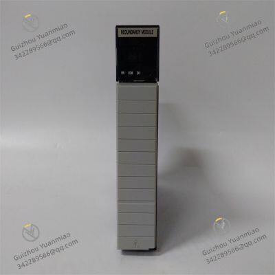
1756-RM is a key redundancy module in Rockwell Automation's ControlLogix series. Its main function is to provide redundancy management and switchover control for ControlLogix redundant systems, ensuring that when the main controller or key components fail, the system can quickly switch to standby equipment, maintaining the continuous operation of the automated control system. It is a core component for improving system reliability and availability.
This module is seamlessly compatible with redundant controllers, power modules, racks, and other equipment in the ControlLogix series. It realizes functions such as fault detection and automatic switchover by real-time monitoring the operating status of the main and standby systems. With its efficient redundancy management capability, fast switchover response, and stable operation performance, 1756-RM is widely used in industrial scenarios with extremely high requirements for system continuity, such as chemical production process control, power system automation, and large-scale oil and gas processing facilities. In these scenarios, any system interruption may cause serious safety accidents or huge economic losses.

II. Technical Parameters
Redundancy type support: Supports controller redundancy and power supply redundancy of the ControlLogix system. It can monitor and manage the operating status of the main and standby controllers and main and standby power supplies in real-time, ensuring effective redundancy backup of key components.
Switchover time: When the main system fails, the time to switch to the standby system is extremely short, usually at the millisecond level (specific time is subject to the product manual). This can minimize system interruption time and ensure the continuity of the production process.
Communication interface: Communicates with controllers, power supplies, and other modules in the redundant system through the ControlLogix backplane bus, transmitting status information and control commands. The communication rate is high and stable, ensuring the real-time and accuracy of redundancy management.
Power supply requirements: Powered by the power module of the ControlLogix rack, with a typical supply voltage of 5V DC. It has low power consumption, has little impact on the system power load, and is convenient for system integration.
Environmental adaptability:
Operating temperature: Can work stably within the temperature range of 0°C - 60°C, adapting to common temperature fluctuations in industrial sites.
Relative humidity: Can operate normally in an environment with a relative humidity of 5% - 95% (non-condensing), suitable for humid production workshops, outdoor control cabinets, and other environments.
Vibration and shock resistance: Complies with relevant industrial standards such as IEC 61131-2, has certain vibration and shock resistance capabilities, and can work reliably in industrial occasions with slight vibrations (such as near production lines and pump sets).
Status indication: Equipped with multiple LED status indicators, which can display the overall status of the redundant system (such as normal, switching, fault, etc.) and the operating status of the main and standby equipment (such as main controller running, standby controller ready, etc.), facilitating operators to intuitively understand the system redundancy situation.

III. Functional Characteristics
Real-time status monitoring: 1756-RM can continuously monitor the operating status of key components such as main and standby controllers and main and standby power supplies, including parameters such as CPU load, communication links, and power supply voltage. It can promptly detect abnormalities and record fault information, providing a basis for system maintenance.
Automatic fault switchover: When a fault is detected in the main controller or main power supply (such as shutdown, communication interruption, power failure, etc.), the module will automatically trigger the switchover mechanism, seamlessly transferring system control to the standby equipment. The entire process requires no manual intervention, ensuring that the system resumes normal operation in an extremely short time and reducing production interruptions caused by faults.
Synchronization management: Responsible for data synchronization between the main and standby controllers, ensuring that the standby controller replicates the program, data, and operating status of the main controller in real-time. When a switchover occurs, the standby controller can seamlessly take over system control, avoiding data loss or confusion in control logic, and ensuring the continuity and consistency of the production process.
Manual switchover function: In addition to automatic switchover, it also supports manual switchover. Operators can trigger the switchover between main and standby equipment through programming software or hardware buttons, facilitating use during system maintenance, upgrades, or testing, and improving the flexibility of system operation.
Fault diagnosis and alarm: Equipped with a complete fault diagnosis function. When an abnormality occurs in the redundant system (such as synchronization failure, standby equipment failure, etc.), it will display the fault status through LED indicators and upload alarm information to the monitoring system through the controller, reminding maintenance personnel to handle it in a timely manner and reducing system risks.
Convenient integration and configuration: Compatible with Rockwell Automation's Logix Designer programming software. Users can configure the redundant system through the software, such as setting switchover conditions and synchronization parameters. The configuration process is simple and intuitive, facilitating rapid deployment and debugging of the system. At the same time, the module adopts a standardized rack mounting method, making the installation process convenient and enabling it to quickly form a redundant system with other redundant components of the ControlLogix series.

IV. Application Scenarios
Chemical production process control: In the control of key equipment such as chemical reactors and distillation towers, system interruption may cause chemical reactions to get out of control and trigger safety accidents. 1756-RM ensures the continuous operation of the control system through redundancy management. When the main controller or power supply fails, it quickly switches to standby equipment, maintaining stable control of parameters such as temperature, pressure, and flow, and ensuring the safety and continuity of chemical production.
Power system automation: In the automation control systems of power plants and substations, 1756-RM is used to ensure the continuity of monitoring and control functions. The power system has extremely high requirements for reliability; any interruption may affect the stability of power supply and even lead to large-scale power outages. Through its redundant design, this module ensures that when the main control equipment fails, the standby equipment can take over immediately, ensuring the normal operation of functions such as power dispatching and equipment monitoring.
Large-scale oil and gas processing facilities: In oil and gas exploration, processing, and transportation facilities, the automation control system is responsible for monitoring key parameters such as pressure, flow, and liquid level, and controlling the operation of valves, pumps, and other equipment. The redundancy function of 1756-RM can avoid serious consequences such as oil and gas leaks and equipment damage caused by system failures, ensuring the continuity and safety of the oil and gas processing process.
Urban water supply and sewage treatment: In the automation control of urban water supply systems and sewage treatment plants, system interruption may affect water supply quality or cause substandard sewage treatment. 1756-RM ensures the continuous operation of the control system through redundancy management, ensuring the normal operation of water pumps, valves, aeration equipment, etc., and maintaining the stability of water supply and sewage treatment processes.

V. Common Faults and Solutions
Redundancy switchover failure
Phenomenon: When the main controller or power supply fails, the system fails to switch to the standby equipment successfully, leading to system interruption, and the fault indicator of the redundancy module lights up.
Causes and solutions:
Standby equipment failure: The standby controller or power supply itself has a fault and cannot take over the system normally. Check the operating status of the standby equipment, repair or replace the faulty standby equipment, and ensure that the standby system is in a ready state.
Synchronization failure: Data synchronization between the main and standby controllers fails, causing the standby equipment to be unable to obtain the latest operating data and programs. Check the communication link between the main and standby controllers to ensure reliable connection; restart the synchronization process through programming software and check whether the synchronization parameter configuration is correct.
Redundancy module failure: 1756-RM itself has a fault and cannot execute the switchover logic normally. Contact professional maintenance personnel to inspect the module and replace the redundancy module if necessary.
Abnormal display of main/standby status
Phenomenon: The main/standby status displayed by the LED indicators of the redundancy module is inconsistent with the actual situation. For example, the actual main controller is running normally, but the indicator shows the standby status, or the main/standby status switches frequently and irregularly.
Causes and solutions:
Fault in the status monitoring circuit: The circuit inside the module used to monitor the main/standby status is faulty, leading to incorrect status judgment. Contact professional maintenance personnel to inspect the internal circuit of the module, repair or replace faulty components.
Communication interference: The communication between the redundancy module and the main/standby equipment is subject to electromagnetic interference, resulting in errors in status information transmission. Take shielding measures (such as using shielded cables, adding grounding) to reduce electromagnetic interference in the surrounding environment; check the connection of communication lines to ensure reliable contact.
Incorrect parameter configuration: The status monitoring parameters of the redundancy module (such as heartbeat detection time, fault judgment threshold, etc.) are configured unreasonably, leading to status misjudgment. Reconfigure the parameters through programming software to make them meet the actual operating requirements of the system.
Inability to perform manual switchover
Phenomenon: When the operator triggers manual switchover through programming software or hardware buttons, the system has no response, and the main/standby status does not change.
Causes and solutions:
Manual switchover permission not enabled: The manual switchover permission is not enabled in the programming software, resulting in the operation being prohibited. Enter the software configuration interface, check and enable the manual switchover permission.
Switchover command transmission failure: The manual switchover command is interrupted or has errors during transmission and is not received by the redundancy module. Check the command transmission path (such as software communication link, hardware button connection), repair communication faults, or replace damaged buttons.
Standby equipment not ready: The standby equipment is in an unready state (such as starting up, having faults) and cannot receive the switchover command. Wait for the standby equipment to complete startup or eliminate its faults, and ensure that the standby equipment is in a ready state before performing manual switchover.
Allen-Bradley 1756-RM2 ControlLogix Redundancy Module
Allen-Bradley 1336-BDB-SP46D Pcb Circuit Board
Allen-Bradley 1336-PB-SP11A Advanced Control Module
Allen-Bradley 1336-SN-SP10A Adjustable Frequency AC Drive
Allen-Bradley 1404-M405A-DNT Powermonitor 3000 Module
Allen-Bradley 1715-OB8DE ControlLogix I/O Module


Allen-Bradley 1753-L32BBBM-8A Safety Controller
Allen-Bradley 1761-L32AWA Controller
Allen-Bradley 1766-L32BXBA MicroLogix 1400 Controller
Allen-Bradley 1768-L43 CompactLogix Controller
Allen-Bradley 1783-MX08T Ethernet Managed Switches
Allen-Bradley 1783-MS10T Ethernet Managed Switches
Allen-Bradley 1786-RPFPXLB ControlLogix Processor Module
Allen-Bradley 1398-DDM-075 Ultra Series Servo Drive
Allen-Bradley 1784-KTX Communication Interface Card
Allen-Bradley 1784-PCIC Communication Interface Card
Allen-Bradley 1784-PKTX Network Interface Card
Allen-Bradley 1797-PS2E2 FLEX Ex Power Supply Module
Allen-Bradley 2094-BC04-M03-S Kinetix 6000 Integrated Axis Module
Allen-Bradley 2094-BM01-S Class Axis Module
Allen-Bradley 2094-EN02D-M01-S1 Kinetix 6200/6500 Control Module
Allen-Bradley 2098-DSD-020X Ultra 3000 Digital Servo Drive
Allen-Bradley 5204-DFNT-PDPMV1 EtherNet/IP Communication Module
Allen-Bradley 5302-MBP-MCM4MB EtherNet/IP Communication Module
 yezi
Hi there! Welcome to my shop. Let me know if you have any questions.


