
- Ningbo Yuantao Import&Export Co.,Ltd.
-
Ningbo, Zhejiang, China
- Main products: Flowmeters, Level Transmitters, Pressure Transmitters, analytics, valve, pump
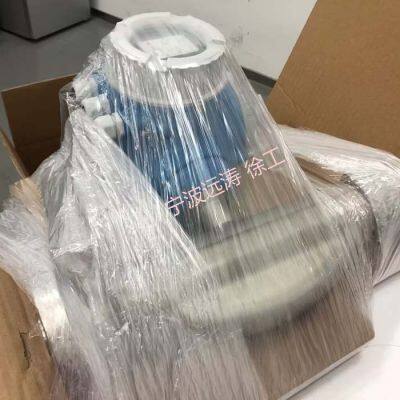
Endress+Hauser Electromagnetic Flowmeters
You May Like
Product Details
| Brand Name | Endress+Hauser | Place of Origin | Germany |
Product Description
Technical Article on Endress+Hauser Electromagnetic Flowmeters
Introduction
Electromagnetic flowmeters, abbreviated as EMFs, are a type of flow measurement instrument that has developed rapidly since the 1950s and 1960s with advancements in electronic technology. These instruments utilize the principle of electromagnetic induction to measure the flow rate of conductive fluids based on the electromotive force (EMF) induced when the fluid passes through an external magnetic field. Among the various manufacturers of electromagnetic flowmeters, Endress+Hauser (E+H) stands out as a renowned company known for its high-quality and innovative products in this field. This article delves into the technical aspects of E+H Electromagnetic Flowmeters, exploring their working principles, components, applications, advantages, disadvantages, and operational methods.
Working Principle
The working principle of Endress+Hauser Electromagnetic Flowmeters is based on Faraday's Law of Electromagnetic Induction, which states that an electromotive force is induced in a conductor moving through a magnetic field. Specifically, when a conductive fluid flows through a pipe placed in a magnetic field, the moving ions in the fluid cut across the magnetic field lines, inducing an EMF between electrodes placed perpendicular to both the fluid flow and the magnetic field. The magnitude of this induced EMF is directly proportional to the fluid's velocity, allowing for the calculation of flow rate.
Components
Endress+Hauser Electromagnetic Flowmeters consist of several key components that work together to ensure accurate flow measurement:
Magnetic Field System: This component generates a uniform magnetic field within the measurement pipe. Typically, an alternating magnetic field is used, which is produced by an electromagnetic coil powered by a 50Hz AC source. The alternating field prevents electrode polarization and is more economically feasible for larger pipe diameters.
Measurement Tube: This is the conduit through which the conductive fluid flows. It is made of non-magnetic, low-conductivity, and low-thermal conductivity materials such as stainless steel, fiberglass, high-strength plastics, or aluminum to prevent magnetic flux leakage and ensure accurate measurement.
Electrodes: Electrodes are installed on the inner wall of the measurement tube and serve to pick up the induced EMF. They are generally made of non-magnetic stainless steel and are flush with the lining to avoid obstructing fluid flow. The electrodes are typically arranged in a way that allows for the measurement of the EMF generated perpendicular to the fluid flow and the magnetic field.
Converter: The induced EMF signal generated by the fluid flow is very weak and susceptible to interference. The converter amplifies this signal, converts it into a standardized output, and filters out noise. It may also perform temperature and pressure compensation to improve measurement accuracy. The converter often includes a high-performance microprocessor for signal processing and display functions.
Lining and Housing: The lining inside the measurement tube is made of corrosion-resistant, high-temperature-resistant, and wear-resistant materials such as Teflon or ceramic. It protects the tube from the measured fluid and prevents the induced EMF from being short-circuited by the metal tube wall. The housing, made of ferromagnetic material, houses the excitation coils and shields the system from external magnetic field interference.
Measurement Principle in Detail
According to Faraday's Law, the EMF (e) induced in a conductor moving through a magnetic field is given by the equation:
e = Blv
where:
e is the induced EMF,
B is the magnetic flux density,
l is the length of the conductor in the magnetic field,
v is the velocity of the conductor perpendicular to the magnetic field.
In the context of an electromagnetic flowmeter, the conductive fluid in the pipe acts as the conductor, the magnetic field is produced by the magnetic field system, and the electrodes measure the induced EMF. For a pipe with an inner diameter D and a uniform flow velocity u, the volume flow rate (qv) can be calculated as:
qv = πD2u/4
Since the induced EMF e is proportional to the fluid velocity u, and the volume flow rate qv is proportional to u, it follows that the induced EMF is also related to the flow rate. By measuring the EMF, the flow rate can be determined.
It is important to note that for this equation to hold true, certain assumptions must be met:
The magnetic field must be uniformly distributed and constant.
The fluid velocity distribution must be axisymmetric.
The fluid must be non-magnetic.
The fluid's electrical conductivity must be uniform and isotropic.
Advantages
Endress+Hauser Electromagnetic Flowmeters offer numerous advantages that make them ideal for various industrial applications:
Accuracy and Reliability: The measurement principle is based on Faraday's Law, which ensures high accuracy and reliability. The flowmeters are designed with advanced signal processing techniques to minimize errors and improve measurement performance.
Wide Measurement Range: Electromagnetic flowmeters can measure a wide range of flow rates, with a turndown ratio of up to 150:1. This makes them suitable for applications with varying flow conditions.
Versatility: They can measure a variety of conductive fluids, including liquids with high viscosity, slurries, and aggressive chemicals. With the right choice of lining and electrode materials, they can withstand corrosion and wear.
No Pressure Loss: Since there are no moving parts or obstructions in the flow path, electromagnetic flowmeters cause no pressure loss. This is particularly advantageous in applications where pressure drop needs to be minimized.
Long Lifespan: The absence of moving parts also means that electromagnetic flowmeters have a long lifespan and require minimal maintenance.
Bidirectional Measurement: Many models can measure flow in both directions, providing valuable information on reverse flow conditions.
Advanced Communication Interfaces: E+H flowmeters support various communication protocols such as HART, Modbus, and Profibus, allowing for easy integration into automation systems.
Operational Methods
Operating an E+H Electromagnetic Flowmeter involves several steps, including installation, commissioning, and routine maintenance.
Installation:
Selection of Installation Location: The flowmeter should be installed in a straight pipe section with a minimum length of 5 pipe diameters upstream and 2 pipe diameters downstream to ensure accurate measurement. The installation location should be free from vibrations and strong magnetic fields.
Mounting: The flowmeter should be mounted in such a way that the electrodes are at the same level to prevent the accumulation of sediment on the electrodes, which could affect measurement accuracy. The flowmeter should also be grounded properly to prevent electrical interference.
Fluid Conditions: The fluid should be fully filled in the pipe to avoid air bubbles adhering to the electrodes, which could cause measurement errors. If the fluid is not fully filled, the outlet pipe height can be raised to ensure that the fluid is fully filled.
Contact Us

- Ningbo Yuantao Import&Export Co.,Ltd.
- Contact nameNick Xu Chat Now
- AddressYinzhou District, Ningbo, Zhejiang
New Products
-
Endress+Hauser Guided Radar Level Transmitters
-
Endress+Hauser Ultrasonic Level Transmitters
-
Endress+Hauser Pressure Transmitters
-
Endress+Hauser Differential Pressure Transmitters
-
Endress+Hauser Temperature Transmitters
-
Endress+Hauser pH Sensors
-
Endress+Hauser Dissolved Oxygen Sensors
-
Endress+Hauser Conductivity Sensors
-
Endress+Hauser Turbidity Sensors
-
Rosemount Flowmeters
-
Rosemount Electromagnetic Flowmeters
-
Rosemount Vortex Flowmeters
Popular Searches
- air flow meter
- hour meter
- digital clamp meter
- temperature meter
- meter counter
- energy meter
- clamp meter
- flow meter
- air flowmeter
- ultrasonic flow meter
- water flow meter
- turbine flow meter
- sewage flow meter
- vortex flow meter
- ac clamp meter
- magnetic flow meter
- alcohol meter
- correction liquid
- water flowmeter
- flow sensor water
- liquid control meter
- oil flow meter
- flow measurement
- water flow rate meter
- flow indicator
- liquid flowmeter
- fuel flow sensor
- liquid meter
- flow measuring flowmeter
- gear flow meter
Recommended Products
- Digital LCD Display Volumetric Rotary Gas Meter for Natural Gas
- Factory High Accuracy Digital Natural Gas Roots Flowmeter
- 1.0% Accuracy Digital Integrated Gas Ultrasonic Flow Meter for Natural Gas
- Industial High Accuracy Digital Gas Ultrasonic Flow Meter
- Industrial Digital Integrated RS485 Compressed Gas Air Ultrasonic Flow Meter
- Digital High Precision Field Display Pipeline Air Ultrasonic Flow Meter
- Explosion-proof Flange Connection Gas Ultrasonic Flowmeter With RS485 Hart GPRS
- Explosion-Proof Digital High Accuracy 4-20mA Gas Turbine Flowmeter
- High Quality RS485 GPRS Digital Fuel Gas Turbine Flow Meter
- Petroleum and Chemical Industry RS485 Turbine Gas Flowmeter for LPG CNG
- High Accuracy Digital Stainless Steel Natural Gas Flow Meter With Oil Cup
- High Precision LCD Display Aluminium Allouy Gas Turbine Flow Meter
Find Similar Products By Category
- Instruments & Meters > Meter for Liquid & Gas > Flow Meter
Product Tags:
Ningbo Yuantao Import&Export Co.,Ltd.

- Please Enter your Email Address
- Please enter the content for your inquiry.
We will find the most reliable suppliers for you according to your description.
Send Now-
 Nick Xu
Hi there! Welcome to my shop. Let me know if you have any questions.
Nick Xu
Hi there! Welcome to my shop. Let me know if you have any questions.
Your message has exceeded the limit.
- Contact supplier for lowest price
- Customized Request
- Request Sample
- Request Free Catalogs
Your message has exceeded the limit.
-
Purchase Quantity
-
*Sourcing Details
Your inquiry content must be between 10 to 5000 characters.
-
*Email
Please enter Your valid email address.
-
Mobile